 Facebook
 Google
 GitHub
 Linkedin
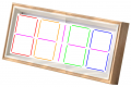
Hi all, I'm designing a Power Distribution and Controller PCB for a Clock/LED Display frame and I'm looking for some guidance on the best combination of power supply and PCB layout. I've designed a PCB with 21 WS2815 LEDs and will have a 3D printed frame panel that will hold the boards in the number configuration you see in the attached pics. I plan on selling this as a product and hopefully manufacturing many, so total cost matters.
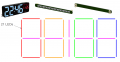
My plan was to have a barrel connector and place the PCB at the edge of the frame allowing a power supply brick to be connected similar to a laptop charger. There are a total of 630 LEDs and I split the layout into 5 strings of 126 LEDs, shown in different colors, each string will get their own power injection from the PCB. The board will also have an ESP32 which I will use to control the LEDs.
I'm a bit new to PCB and product design, and I'm not sure what is the best combination between power supply and PCB layout. WS2815 operate at 12V and I found this article that claims they consume 60mA at max brightness. Having a 450W power supply for a product like this sounds insane though, so I'm ok with LEDs not reaching max brightness. I think it's important to note that the clock display wouldn't have all LEDs on at the same time, but other full display patterns will.
- I did some research online and found that some gaming laptops have 150w and 200w power supplies, is it common for lighting products with a lot of LEDs to also have such high wattage power supplies?
- Is it more cost effective to buy a unique power supply that outputs 12V at high currents and keep the PCB layout simple, or have a more standard high voltage power supply with buck converters on the PCB?
- Should all 5 branches draw form one 12V high Amp source or have their own regulators with capped currents?
- Are there any safety regulations or design requirements I should be considering for a product like this?
Attachments
-
 347.1 KB Views: 7
 -
 98 KB Views: 7


