Facebook
 Google
 GitHub
 Linkedin

Hi!
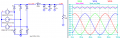
I’m simulating a three-phase rectifier with diodes and an R-78HE5.0-0.3 DC-DC converter in LTSpice.
The three sine waves come from a three-phase motor which I assume runs at 15 Hz, so with 8 pole pairs that’s approximately 111 rpm (this is just an example)
---------------------------------------------1---------------------------------------------
Can I simulate the DC-DC converter by replacing it with an equivalent resistor?
If I know its output voltage (5V) and current (300mA), assuming an efficiency of 85% and a rectified input voltage of 48V, can I calculate a resistor to ‘replace’ it in the simulation?
Po = Vo * Io = 5 * 0.3 = 1.5W
Pi = Po / n = 1.5 / 0.85 = 1.765W
Ri = Vi^2 / Pi = 48 / 1.765 = 1305 ohm
I am aware that real DC-DC converters behave like a negative differential resistor (if the input voltage rises, the input current falls to keep the power constant), while a fixed resistor behaves in the opposite way... but I am assuming fixed values to maintain a constant equivalent resistance under such conditions
---------------------------------------------2---------------------------------------------
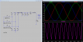
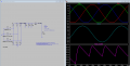
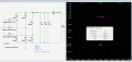
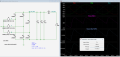
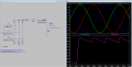
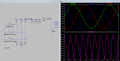
If my calculation is correct, I end up with an output that hasn’t been rectified properly:
View attachment 370225
Apart from increasing the capacitance, what can I do to reduce ripple?
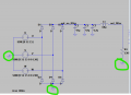
(I’ve included L1 (which has no effect in this circuit) because I’d like to test and understand which CLC filter to use at the input to the DC-DC converter, given that it’s recommended in the event of EMI)
---------------------------------------------3---------------------------------------------
I’m afraid I might be doing something wrong when setting up the three input generators
I’m simulating a three-phase rectifier with diodes and an R-78HE5.0-0.3 DC-DC converter in LTSpice.
The three sine waves come from a three-phase motor which I assume runs at 15 Hz, so with 8 pole pairs that’s approximately 111 rpm (this is just an example)
---------------------------------------------1---------------------------------------------
Can I simulate the DC-DC converter by replacing it with an equivalent resistor?
If I know its output voltage (5V) and current (300mA), assuming an efficiency of 85% and a rectified input voltage of 48V, can I calculate a resistor to ‘replace’ it in the simulation?
Po = Vo * Io = 5 * 0.3 = 1.5W
Pi = Po / n = 1.5 / 0.85 = 1.765W
Ri = Vi^2 / Pi = 48 / 1.765 = 1305 ohm
I am aware that real DC-DC converters behave like a negative differential resistor (if the input voltage rises, the input current falls to keep the power constant), while a fixed resistor behaves in the opposite way... but I am assuming fixed values to maintain a constant equivalent resistance under such conditions
---------------------------------------------2---------------------------------------------
If my calculation is correct, I end up with an output that hasn’t been rectified properly:
View attachment 370225
Apart from increasing the capacitance, what can I do to reduce ripple?
(I’ve included L1 (which has no effect in this circuit) because I’d like to test and understand which CLC filter to use at the input to the DC-DC converter, given that it’s recommended in the event of EMI)
---------------------------------------------3---------------------------------------------
I’m afraid I might be doing something wrong when setting up the three input generators
Attachments
-
2.4 KB Views: 6
-
 72.9 KB Views: 12
Last edited: