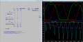
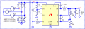
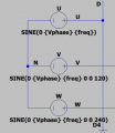
1. Leave the junction of the voltage sources grounded so they behave correctly as AC voltage generators.
2. You can remove the ground from the diodes but then the diode junction must becomes a "neutral" node, so the filter caps and load resistor will need to be reconnected to "neutral". Also, use diodes with models (for example, 1N4007).
3-phase voltage sources with Isolated or grounded neutral work identically,
but rest of circuit, after diode bridge, should be grounded for simulation:
As was already mentioned a few times, the voltage sources should not be grounded. If you do that anyway, hundreds of amps are driven through the now redundant bottom diodes during the negative half wave(s) and you are left with half wave rectification.
The line-to-line RMS voltage VL_rms is already off which leads to the wrong average DC output voltage Vdc. Only 48V DC left? How or where are ~5.8V "lost"?
As was already mentioned a few times, the voltage sources should not be grounded. If you do that anyway, hundreds of amps are driven through the now redundant bottom diodes during the negative half wave(s) and you are left with half wave rectification.
No. The diodes, filter and load should be referenced to "neutral" instead of simulator ground.
The line-to-line RMS voltage VL_rms is already off which leads to the wrong average DC output voltage Vdc. Only 48V DC left? How or where are ~5.8V "lost"?
The whole point of this is to produce 48vdc out with some ripple into a 1305 ohm load (load acting as an SMPS).
I don't know what the filter is supposed to represent.
A DC voltage source could have been used with some ripple added, instead of using an three phase AC source.
The whole point of this is to produce 48vdc out with some ripple into a 1305 ohm load (load acting as an SMPS).
I don't know what the filter is supposed to represent.
Hi!
I’m simulating a three-phase rectifier with diodes and an R-78HE5.0-0.3 DC-DC converter in LTSpice.
The three sine waves come from a three-phase motor which I assume runs at 15 Hz, so with 8 pole pairs that’s approximately 111 rpm (this is just an example)
---------------------------------------------1---------------------------------------------
Can I simulate the DC-DC converter by replacing it with an equivalent resistor?
I’m afraid I might be doing something wrong when setting up the three input generators
Do you really mean a generator rather than motor? A 15Hz 8 pole synchronous machine will run at 225RPM (RPM=120*f / POLES)
Machines are rated with line to line (L-L) RMS voltage and Line RMS current no matter how the windings are connected. The output terminals are T1, T2, & T3. If the other end of the windings are brought out they will be T4, T5 & T6.
Others have pointed out that the generator neutral must not be connected to the common (either pole) of a full wave rectifier or to any other node in the circuit. Generally, power rectifiers are fed from a dedicated transformer that is either a delta or wye connected and is ungrounded. For actual physical equipment the actual circuit ground is somewhere after the rectifier. Placement of the ground terminal can make making measurements difficult since Spice uses circuit ground as the reference.
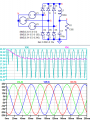
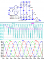
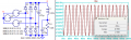
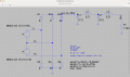
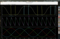
A generalized 3 phase generator using V peak and f as input parameters is used in the circuit below. I've also generalized the output filter. The frequency was picked to make the important places on the 3 phase waveform line up with the grid.
Since the generator neutral can't be connected to any part of the circuit, it isn't modeled. You can experiment with different filter arrangements by changing the appropriate param values.
You may need a better DC-DC converter model since some filter settings may interact with the switching devices in the converter. The input phase currents are nasty and will produce all sorts of harmonics that will cause increases losses in a real rotating machine or transformer.
First time posting images so apologies if they're too big/small/wrong format, etc.
Do you really mean a generator rather than motor? A 15Hz 8 pole synchronous machine will run at 225RPM (RPM=120*f / POLES)
Machines are rated with line to line (L-L) RMS voltage and Line RMS current no matter how the windings are connected. The output terminals are T1, T2, & T3. If the other end of the windings are brought out they will be T4, T5 & T6.
Others have pointed out that the generator neutral must not be connected to the common (either pole) of a full wave rectifier or to any other node in the circuit. Generally, power rectifiers are fed from a dedicated transformer that is either a delta or wye connected and is ungrounded. For actual physical equipment the actual circuit ground is somewhere after the rectifier. Placement of the ground terminal can make making measurements difficult since Spice uses circuit ground as the reference.
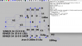
A generalized 3 phase generator using V peak and f as input parameters is used in the circuit below. I've also generalized the output filter. The frequency was picked to make the important places on the 3 phase waveform line up with the grid.
Since the generator neutral can't be connected to any part of the circuit, it isn't modeled. You can experiment with different filter arrangements by changing the appropriate param values.
You may need a better DC-DC converter model since some filter settings may interact with the switching devices in the converter. The input phase currents are nasty and will produce all sorts of harmonics that will cause increases losses in a real rotating machine or transformer.
First time posting images so apologies if they're too big/small/wrong format, etc.
When you say we need better DC-DC modeling, do you happen to know how to do it?
The only thing I've thought of is trying different resistor values, simulating a current draw that varies over time.
I would also like to understand if a possible filter could create stability for the switching power supply that I use.
Do you really mean a generator rather than motor? A 15Hz 8 pole synchronous machine will run at 225RPM (RPM=120*f / POLES)
Machines are rated with line to line (L-L) RMS voltage and Line RMS current no matter how the windings are connected. The output terminals are T1, T2, & T3. If the other end of the windings are brought out they will be T4, T5 & T6.
Others have pointed out that the generator neutral must not be connected to the common (either pole) of a full wave rectifier or to any other node in the circuit. Generally, power rectifiers are fed from a dedicated transformer that is either a delta or wye connected and is ungrounded. For actual physical equipment the actual circuit ground is somewhere after the rectifier. Placement of the ground terminal can make making measurements difficult since Spice uses circuit ground as the reference.
A generalized 3 phase generator using V peak and f as input parameters is used in the circuit below. I've also generalized the output filter. The frequency was picked to make the important places on the 3 phase waveform line up with the grid.
Since the generator neutral can't be connected to any part of the circuit, it isn't modeled. You can experiment with different filter arrangements by changing the appropriate param values.
You may need a better DC-DC converter model since some filter settings may interact with the switching devices in the converter. The input phase currents are nasty and will produce all sorts of harmonics that will cause increases losses in a real rotating machine or transformer.
First time posting images so apologies if they're too big/small/wrong format, etc.
One more question: why are C1 and L2 in the filter you included only 1 pF and 1 nF, respectively? Are they almost negligible in the circuit?
If I'm right, then it's a simple low-pass filter consisting of C2 and L1
If I'm wrong, though, I don't understand the cutoff frequency and the "topology" of the filter... it looks like a pi-filter with an inductor added at the end. Or two CL-CL high-pass filters
One more question: why are C1 and L2 in the filter you included only 1 pF and 1 nF, respectively? Are they almost negligible in the circuit?
If I'm right, then it's a simple low-pass filter consisting of C2 and L1
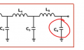
It is impossible - "no capacitor", because any load has its own capacitance.
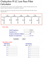
Therefore, when calculate, use input capacitance of your SMPS as last capacitor of filter.
I didn't intend the L C arrangement to be any particular filter.
The C1, L1, C2, L2 arrangement allows trying different arrangements and sizes of C & L without editing the schematic.
Rather than add or remove parts by editing the diagram, you add or remove by changing the value. Since Spice won't allow 0 values you pick very small values to remove the part from the circuit. For me, that is faster than editing the circuit diagram. Prior to Sept. '25 the only circuit simulation available to me was command line Spice where iterating a circuit topology could result in leaving out or adding spurious connections.
One drawback is that having a mix of regular and very small parts slows the computation.
It is somewhat like grounding thru a 10M or 10T resistor. The part satisfies Spice's requirement for a ground without actually grounding the circuit.
When you say we need better DC-DC modeling, do you happen to know how to do it?
The only thing I've thought of is trying different resistor values, simulating a current draw that varies over time.
My hunch is that the DC-DC converter has a similar topology to a SMPS. I would model at least the input switching components or some sort of stand in that includes the input filter and a PWM load to introduce the high frequency pulsating current and /or voltage.
My experience with SMPS is very minimal (actually non-existent) and I would look to models of commercial products for guidance.
Any commercial DC-DC converter will have an input filter or a requirement of a certain capacitance at the input. It may also specify avoidance of a range of capacitance. Any inductance in your filter will interact with the DC-DC converter input and the switching frequency may (probably will) excite undesirable behavior.
Looking at the datasheet for an LM2576 (picked at random) , I would try to model the circuit at the output driven by a simple PWM switching device in place of the LM2576 as a beginning attempt. Maybe just the output circuit first then add the switch. When the switch is closed the output (pin 2) is attached to your DC supply, when the switch is open, your supply is disconnected. This happens at a very high frequency compared to your generator.
I didn't check but I suspect that there are Spice models of DC-DC converters available from manufacturers.
Browsing the datasheet I note that the input cap is required and the text makes clear that inductance at the input is not your friend. Maybe just avoiding inductance in your filter is enough and a resistor is a good enough model. I don't have the experience to say one way or another.
3-phase voltage sources with Isolated or grounded neutral work identically,
but rest of circuit, after diode bridge, should be grounded for simulation: View attachment 370372View attachment 370373
Do you really mean a generator rather than motor? A 15Hz 8 pole synchronous machine will run at 225RPM (RPM=120*f / POLES)
Machines are rated with line to line (L-L) RMS voltage and Line RMS current no matter how the windings are connected. The output terminals are T1, T2, & T3. If the other end of the windings are brought out they will be T4, T5 & T6.
Others have pointed out that the generator neutral must not be connected to the common (either pole) of a full wave rectifier or to any other node in the circuit. Generally, power rectifiers are fed from a dedicated transformer that is either a delta or wye connected and is ungrounded. For actual physical equipment the actual circuit ground is somewhere after the rectifier. Placement of the ground terminal can make making measurements difficult since Spice uses circuit ground as the reference.
A generalized 3 phase generator using V peak and f as input parameters is used in the circuit below. I've also generalized the output filter. The frequency was picked to make the important places on the 3 phase waveform line up with the grid.
Since the generator neutral can't be connected to any part of the circuit, it isn't modeled. You can experiment with different filter arrangements by changing the appropriate param values.
You may need a better DC-DC converter model since some filter settings may interact with the switching devices in the converter. The input phase currents are nasty and will produce all sorts of harmonics that will cause increases losses in a real rotating machine or transformer.
First time posting images so apologies if they're too big/small/wrong format, etc.

 Facebook
 Google
 GitHub
 Linkedin