Correct means to lower/set input impedance of parallel opamp inputs?

Thread Starter

Schluppy

Joined Jun 7, 2024
38
Hey all,

Another newb question...

Say I want to split a signal from one low impedance source to two unknown impedance inputs via two non-inverting unity gain opamps.

Like so;
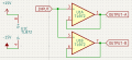
20260726.Opamp_Impedance.001.png

What's the correct way to lower/set the input impedance of each opamp? Assume I want a 1M impedance for each opamp and seek to minimize any interaction between them and the input signal source (if that even matters?).

Can I throw a 1M resistor in series with each non-inverting input? Or, perhaps a 1M (2M?) resistor from the signal to ground? Something else?

Thanks!
 

BobTPH

Joined Jun 5, 2013
11,600
You do not need to and should not lower it.

A low impedance driving a high impedance is the desired configuration for feeding a signal to an input. That way, the voltage of the signal is not affected. If you matched the impedance, it would cut the signal in half.

The max power theorem is about power transfer, not signal propagation. The exception being RF signals, where mismatched impedances causes reflections which distort the signal.

Edited to add: That said, if you ever need to lower the impedance of an input, simply put a resistor in parallel with it.
 

Thread Starter

Schluppy

Joined Jun 7, 2024
38
You do not need to and should not lower it.
That probably explains why it's been so difficult to find information about it. :)
That said, if you ever need to lower the impedance of an input, simply put a resistor in parallel with it.
So, in this instance with parallel inputs, a 1M from the signal INPUT to, say, GND would get me 1M input impedance on each input?
 

BobTPH

Joined Jun 5, 2013
11,600
That probably explains why it's been so difficult to find information about it. :)


So, in this instance with parallel inputs, a 1M from the signal INPUT to, say, GND would get me 1M input impedance on each input?
Only if the intrinsic impedance is much greater than that. You have two resistors in parallel.
 

Thread Starter

Schluppy

Joined Jun 7, 2024
38
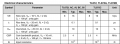
The op amp data sheet will tell you that.
Could I trouble you for a link, if available, to the datasheet you pulled that table from?

The datasheet I've been referencing (from TI) does not contain that table. Instead, on page 15, it lists the Common Mode Input Resistance (RID) as 1TΩ. So, the values match but I'm curious to see other differences between the datasheet versions -- might be more information to glean.
 

JTEX

Joined Mar 19, 2026
12
Assuming you're dealing with audio-band frequencies, most single op amps can easily drive several typical audio inputs in parallel (unless they're super low impedance, like headphones). It doesn't matter if the downstream audio inputs have different impedances - the op amp's output impedance is effectively zero, and both inputs will see the same voltage.

Not sure why you need two op amps in the first place - unless you want separate gains for each output, which doesn't seem to be the case.
 

Thread Starter

Schluppy

Joined Jun 7, 2024
38
Assuming you're dealing with audio-band frequencies [...]
Your assumption is correct. Specifically, guitar.

Not sure why you need two op amps in the first place - unless you want separate gains for each output, which doesn't seem to be the case.
Primarily because I had an extra opamp.

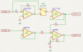
My original design was much like you suggest; split after a single buffer. To illustrate (forgive the hastily drawn schematic);

20260805.four.opamps.png

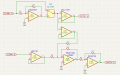
Then I started reading about some of the negative effects of a non-inverting summing configuration. Namely cross-talk and gain changes when an input is disconnected. So, I changed the summer to an inverting configuration and added another stage to invert the summed signal back to its original polarity. Like so (again, hastily drawn);

20260805.six.opamps.png


As I'm using dual opamp packages, this scheme provided me with a bonus opamp which I thought I may as well put to use in the splitter.
 
Top