DC-DC input resistance for LTSpice simulation

Thread Starter

andrew74

Joined Jul 25, 2022
252
Hi!
I’m simulating a three-phase rectifier with diodes and an R-78HE5.0-0.3 DC-DC converter in LTSpice.
The three sine waves come from a three-phase motor which I assume runs at 15 Hz, so with 8 pole pairs that’s approximately 111 rpm (this is just an example)

---------------------------------------------1---------------------------------------------
Can I simulate the DC-DC converter by replacing it with an equivalent resistor?

If I know its output voltage (5V) and current (300mA), assuming an efficiency of 85% and a rectified input voltage of 48V, can I calculate a resistor to ‘replace’ it in the simulation?

Po = Vo * Io = 5 * 0.3 = 1.5W
Pi = Po / n = 1.5 / 0.85 = 1.765W
Ri = Vi^2 / Pi = 48 / 1.765 = 1305 ohm

I am aware that real DC-DC converters behave like a negative differential resistor (if the input voltage rises, the input current falls to keep the power constant), while a fixed resistor behaves in the opposite way... but I am assuming fixed values to maintain a constant equivalent resistance under such conditions

---------------------------------------------2---------------------------------------------
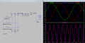
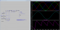
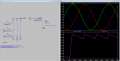
If my calculation is correct, I end up with an output that hasn’t been rectified properly:
View attachment 370225

Apart from increasing the capacitance, what can I do to reduce ripple?
(I’ve included L1 (which has no effect in this circuit) because I’d like to test and understand which CLC filter to use at the input to the DC-DC converter, given that it’s recommended in the event of EMI)

---------------------------------------------3---------------------------------------------
I’m afraid I might be doing something wrong when setting up the three input generators
 

Attachments

Last edited:

crutschow

Joined Mar 14, 2008
38,646
A fixed load resistor should be okay for your simulation purposes.

You reduce ripple (if needed) by increasing the filter capacitance and/or adding a larger inductor (but with the inductor at the input to the capacitors).
There's no other magic to reduce ripple.
 

Thread Starter

andrew74

Joined Jul 25, 2022
252
A fixed load resistor should be okay for your simulation purposes.

You reduce ripple (if needed) by increasing the filter capacitance and/or adding a larger inductor (but with the inductor at the input to the capacitors).
There's no other magic to reduce ripple.
Thank you for your reply.

Have I modelled the three phases of the motor correctly? Because I set it to 48V, but in fact the voltage between phase and neutral fluctuates between -48V and +48V, producing a DC output of around 90V .. which would destroy my DC-DC converter
I’m getting a bit confused by engine theory…

If I remember correctly, in a three-phase system, the peak voltage between two phases is sqrt(3) times the phase voltage … therefore, the three-phase diode bridge brings the DC output to the peak value of the concatenated voltage minus the voltage drop across the two conducting diodes
 
Last edited:

Thread Starter

andrew74

Joined Jul 25, 2022
252
Why are you adding a 48Vdc offset to the sources?
That's why you are getting about 80V in the sim.
The offset should be 0.
Power AC sources have zero offset.
You’re right, offset = 0.

If the voltage formula between phase and neutral is Vdc/2*sin(...) … and my Vdc is 48V … I should set the amplitude to 24V on my three generators, right? … and not 48V

1786209559660.png
 

eetech00

Joined Jun 8, 2013
4,721
Thank you for your reply.

Have I modelled the three phases of the motor correctly? Because I set it to 48V, but in fact the voltage between phase and neutral fluctuates between -48V and +48V, producing a DC output of around 90V .. which would destroy my DC-DC converter
I’m getting a bit confused by engine theory…

If I remember correctly, in a three-phase system, the peak voltage between two phases is sqrt(3) times the phase voltage … therefore, the three-phase diode bridge brings the DC output to the peak value of the concatenated voltage minus the voltage drop across the two conducting diodes
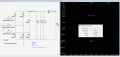
1. Set each sine voltage source to about 36.9v*sqrt(2).
36.9 equals the AC peak of about 48vdc +3v for diode drops.
2. Place a ground at the junction of the voltage sources (Ltspice doesn't care)

1786221371645.png
 

Thread Starter

andrew74

Joined Jul 25, 2022
252
1. Set each sine voltage source to about 36.9v*sqrt(2).
36.9 equals the AC peak of about 48vdc +3v for diode drops.
2. Place a ground at the junction of the voltage sources (Ltspice doesn't care)

View attachment 370236
Hi, I’ll try shortly.
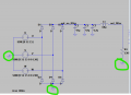
In a three-phase rectifier (leaving aside LTSpice simulation), does the load’s GND coincide with that at the anodes of the diodes and the phases?
@crutschow


1786354487732.png
 
Last edited:

Thread Starter

andrew74

Joined Jul 25, 2022
252
1. Set each sine voltage source to about 36.9v*sqrt(2).
36.9 equals the AC peak of about 48vdc +3v for diode drops.
2. Place a ground at the junction of the voltage sources (Ltspice doesn't care)

View attachment 370236
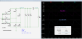
I still have a few doubts about voltage generators.
Let’s assume a PMSM motor with an FOC algorithm (i.e. SVM) and assuming m = 1 .. I know that:

Van = m*Vdc/2*sin(ωt)
Vbn = m*Vdc/2*sin(ωt-2/3π)
Vcn = m*Vdc/2*sin(ωt+2/3π)
So I should set Vdc/2 = 24V for all three voltage sources

Then, the theory tells me that:
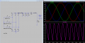
Vab = Van - Vbn = sqrt(3)*Vdc/2*sin(ωt+π/6) = 0.866*Vdc = 41.5V .. and this is what happens in the simulation (see the central sine wave)

The problem is that after the three-phase rectifier, I’m not getting 48V but half that… in other words, the calculations I’ve carried out don’t add up in the simulation.
Using the formulas and assuming Vdc = 48V, I’ve calculated the respective three-phase voltages, but these don’t give me a Vdc of 48V… it doesn’t make sense.

1786356469609.png
 

0ri0n

Joined Jan 7, 2025
181
in other words, the calculations I’ve carried out don’t add up in the simulation.
For some reason you grounded the three voltage sources. D2/D4/D6 will die instantly and, assuming the diodes fail open circuit in real life, you are left with a half-wave rectifier. Look at the frequency of the output voltage ripple .
 

Thread Starter

andrew74

Joined Jul 25, 2022
252
For some reason you grounded the three voltage sources. D2/D4/D6 will die instantly and, assuming the diodes fail open circuit in real life, you are left with a half-wave rectifier. Look at the frequency of the output voltage ripple .
For the sim....yes.
No.
But D2, D4, and D6 definitely will in the real circuit. :eek:
Hi everyone, sorry for the confusion, but in a hypothetical real rectifier, the three diodes aren’t connected to earth, are they?
 
Last edited:

Thread Starter

andrew74

Joined Jul 25, 2022
252
A fixed load resistor should be okay for your simulation purposes.

You reduce ripple (if needed) by increasing the filter capacitance and/or adding a larger inductor (but with the inductor at the input to the capacitors).
There's no other magic to reduce ripple.
I moved the inductor to the position before the three capacitors in parallel, but the ripple doesn’t seem to have changed at all.
To reduce the ripple at such a low frequency, I’m afraid the values of C and L would have to be really high… or am I wrong?
 

eetech00

Joined Jun 8, 2013
4,721
I still have a few doubts about voltage generators.
Let’s assume a PMSM motor with an FOC algorithm (i.e. SVM) and assuming m = 1 .. I know that:

Van = m*Vdc/2*sin(ωt)
Vbn = m*Vdc/2*sin(ωt-2/3π)
Vcn = m*Vdc/2*sin(ωt+2/3π)
So I should set Vdc/2 = 24V for all three voltage sources

Then, the theory tells me that:
Vab = Van - Vbn = sqrt(3)*Vdc/2*sin(ωt+π/6) = 0.866*Vdc = 41.5V .. and this is what happens in the simulation (see the central sine wave)

The problem is that after the three-phase rectifier, I’m not getting 48V but half that… in other words, the calculations I’ve carried out don’t add up in the simulation.
Using the formulas and assuming Vdc = 48V, I’ve calculated the respective three-phase voltages, but these don’t give me a Vdc of 48V… it doesn’t make sense.

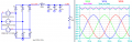
View attachment 370296
DC output Voltage:
1786378512672.png

DC output Power:
1786378558881.png


DC output Ripple Frequency:
1786378710140.png
 
Top