Facebook
 Google
 GitHub
 Linkedin
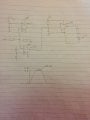
Hey, i would like some assistance with my circuit. I need to design a current cut-off circuit that will disconnect when the current coming into the circuit exceeds 100mA. Also, i would are there any ideas of designing a voltage limiter circuit, it should not allow the voltage to be more than 3.3volts, these are protection circuits for a cold.
Attachments
-
 301 KB Views: 48