After testing the transistor and properly placing the cap check the amp.
IF voltage is not available across that cap, then show me a close up that area.
Here are some things you can do check .
Disconnect power and discharge the caps. Supply filter and 220μf caps
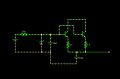
Measure the resistance from point 1 to GND. It should not be too low.
If low resistance is found then there is a short at regulator area or at amp component.
If resistance is high then you should test those 2 tr and the rest of the components.
Remember to solder them properly.
You will get a voltage at point 1 if those regulators are working.
You were right , both the transistors were faulty. There was short between collector and emitter. I replaced them with a more common NPN transistor (BC 547, i know there are not the exact replacement). Now I get different voltages across transistor pins and across the resistors connected to the transistor.
Voltage across pins of transistor with respect to ground are as follows
emiter 11.2 V
collector 18.13 V
base 11.74 V
Unfortunately, I still get only 0.4 V across pin 1 and ground. Very high resistance across pin 1 and ground.
Could please check the circuit I have drawn is correct?
The Led on the remote control turned ON, when I shorted the 5 ohm resistor without any audio output. Also, there were fumes from the board, probably one the transistors burned out again.
I think I have soldered the pins of transistors correctly. The BC 547 and the original transistors have different configurations.
Never short a fusible resistor. Those were low ohms
Check those replaced transistor.
Replace them with proper ratings and the resistors too.
Just to be on the safe side.
U can desolder the amp chip, it is the one taking all the load if faulty.
After checking all the voltages we can replace the chip back.
I bet those transistor got shorted due to heavy collector current.
You can check the standby voltage is switching or not as in the previous post, muting function too.
If those works.
Here is how u could test, provided the amp chip is OK
You have to connect the speakers, but not the woofer.
If all the voltage are fine.
Do not connect any audio input.
Connect the little speakers
Turn the volume to Max.
Take a needle or Pin.
Handle the needle with ur hand, means your skin shud be in contact with needle.
Just simply touch pin 4 of the amp chip.
Don't worry, Voltage levels are safe to handle.
If pin 4 do not produce a noise from the speakers, try pin 5.
Pin 1 is closest to the supply area.
If you can get any sort of noise from the speaker, then you have a preamp issue.
If not it could still be a preamp or the amp chip.
Damn....that's bad
U need to replace anything that is too hot to the touch beside amp chip.
There is no fix around it, since you have said it IS the volume chip.
Remove that chip and try the test again to see if the amp chip is doing fine.
Post the no. of anything and every thing that is too hot to touch when powered
I checked. It is the volume controller. It should never get hot.
It is faulty. Better order one, but check others before that.
It is possible to check
U have to inject sound at the output of volume chip after desoldering it.
Or better yet jump the input to output tracks of the volume chip
when testing this way just keep in mind to have a way to increase the input signal from 0. cause the amp will be working at it's max output
I will try to jumper the I/O of the chip and check. There are two of these chips on board. Does it mean one is for the volume control and the other for the woofer?
After, removing the chip when I tried to power ON, I observed the following things
1. Other volume control chip too became bit warm
2. the LED in the remote did not turn ON. There is still voltage across pin1.
 Facebook
 Google
 GitHub
 Linkedin