Take ur time.
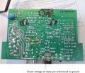
Voltage from 1 and 2 should be referenced to ground.
It should be 0V. If any voltage higher than this IC is faulty.
If not.
I have another voltage measurement, I will post it, U can do it later.
Above pic measurement is if every thing is fine.
The mute and standby pin is marked.
This measurement should be taken referenced to ground and after the caps has been discharged.
Before power up connect meter between mute and ground.
Observe the meter after powering up.
Meter should go from 0 to any voltage above 3V or so.
Rise is slow, as the mute pin is held low to prevent turn on noise. After a few seconds the voltage will rise as the cap connected to this pin charges, disabling the muting ckt.
If this does not rise, then the cap needs to be changed, if cap is OK. IC is faulty. If voltage rises this area is fine.
Next is the standby pin. This pin voltage will switch between 0V and any value higher than that, say 3V.
When u turn off power switch this pin will also switch, putting the IC in stand by.
If this works then on off is OK, But for this u need to disconnect that jumper at the volume control PCB, as u have bypassed the power switch.
If everything passes, I can tell u away to test the power amp IC in circuit
After every thing is OK, then you are having a Muting issue at the preamp stages.
1. There is no voltage across the standby and mute pins with respect to ground pin.
2. There is also no voltage across the capacitor when the circuit is powered ON. The capacitor is fine when checked.
3. Am just curious, why does the power LED in the remote does not turn ON.
4. Also, as I mentioned before if I connect the output from R25 (close to C56) to the volume control switch in remote the LED turn ON. Does it mean that there is no supply to remote, which in turn does not turn on the amplifier circuit.
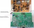
See the pics damaged area.
U have to fix it
The red wires shows jumpers that you have to wire across the yellow circled points.
Do it and check it, keep in mind that the IC gets the standby voltage it will heat up.
It seems and the first jumper which connects the ground there is a low value resistor together with a decoupling cap.
The glue you took away might have them stuck in it.
A jumper will work, worst case will be noise picked at the audio, if this is the case that jumper have to replaced with components.
The first jumper you mentioned actually had a capacitor (C53- 47nf), which broke when I tried to remove the glue. I have placed the jumper as per your suggestion.
Ok then .
If two jumpers are soldered, check for operation.
If not working then check the standby voltage at IC pin and check if there is any voltage at the remote power switch
Yes, Rifa I know to check the transistors. I will check the transistor numbers and find out if its NPN. my guess would be if its NPN it would most probably connected to emitter.
By the way brown wire is connected to last pin from left in the first row.
 Facebook
 Google
 GitHub
 Linkedin