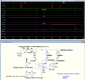
So, continuing with the speculation that the TS wants a game-show circuit, below is my favorite:
It uses only one small SCR, PB sw, and LED per added player.
Just joined. Found a reply for a question over 1 yr ago for a similar problem. Was suggested I create a new post. I need a circuit for the following which I think I can create with relays but prefer not to use them. Using one low voltage (9v likely) source I will have 3 LEDs each with its own switch. Example L1, L2, L3. If any one is of these switches closes and its LED illuminates, the other 2 must cut out - can not come on. So if L2 lights, then circuits for L3 and L1 are broken. I found a similar solution in this YouTube link:
.
The problem here is that when a second light switch is triggered, it can't power up but this config. also kills power to the one that is on. I need the illuminated one to stay on until it is reset. I could wire the Illuminated one to power relays to the other 2 and physically switch them off but this is too complex. Would prefer switches and circuitry if possible.
Thanks for the Welcome but now I am overwhelmed by the forum format and the number of replies. Where can I give an update to my question that all respondees will see? Is that HERE? Thanks to all by the way. I would like to include my first circuit diagram to clarify my request. I can't see how to satisfy it without some sort of relay.
Should I be replying to each of the 20 people who replied separately? How do I abandon a reply I began but want to cancel?
Brewster
You can make a general reply to everybody who opens the post, or you can do a persona message, which I am never sure if they are at a private. AND, you can either post as a reply, or just post by just entering your message without clicking reply.
Thanks for the Welcome but now I am overwhelmed by the forum format and the number of replies. Where can I give an update to my question that all respondees will see? Is that HERE? Thanks to all by the way. I would like to include my first circuit diagram to clarify my request. I can't see how to satisfy it without some sort of relay.
Should I be replying to each of the 20 people who replied separately? How do I abandon a reply I began but want to cancel?
Brewster
Thanks MisterBill2. I will attach my circuit in the next reply from me. It does use relays and I see no other way. The YouTube I had in my question, is pretty much what some others have suggested here but again with any of these, if switch #n is closed after the 1st one, then lamp#n won't go on but lamp#1 goes out. I want it to stay on. Relays will interrupt each circuit independently of the trigger switches. See my next diagram. I still have some questions. I am not an electrician nor an EE so many of the diagrams in these replies are beyond my scope.
Brewster
Mosfet variant of the . . . #6
↑ has a theoretical shortcoming for the occasion where 2 or 3 switches are pushed exactly the same instance
// can be examined if the "switch group" is set to 1 for 2 or more switches ...
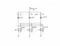
Attached is my original circuit. When I started looking for relays, I encountered terms like backspike which could damage LEDs etc. Transistors (also beyond my grasp) could have heat problems. It was getting too complex for amateur me. So the YouTube video in my original post gave me hope to design a circuit using just hard wired multi throw switches but I could not invent a solution. Attached is my original circuit and any problems you see would be appreciated. If any of S1, S2, or S3 are closed, the corresponding LED will illuminate Their relays are normally closed. With this device, S2 and S3 WILL be powered a mini second later but any one could come on first. That is the one I want to stay on until its S1, S2, or S3 is opened again. EX: if S1 is closed, current will flow through that branch of the circuit but will also power relays 2 and 3 to OPEN their load sides. Hence S2 and S3 become redundant if they close because continuity is broken at the relays. My biggest problem is finding inexpensive small relays. There are tons of switches I can find. The smaller the components the better for this application. Will a 9 volt DC do the trick and power a lamp and both sides of 2 relays? Is there a solid state solution without me getting my Engineering degree? Also concerned that the mechanical relays might not be fast enough.
Thanks
Brewster
Welcome to AAC!
The circuit I posted in this thread should do what you want. You need to remove the unneeded flip flop, replace the 3 input OR with 2 input OR, change the power supply to 9V, and add transistors to drive your LEDs.
Thanks Dennis. I will post my original solution. Not sure what all the symbols are but how compact could this be. I am looking for smal - maybe the size of a hockey puck or two.
Thanks
Attached is my original circuit. When I started looking for relays, I encountered terms like backspike which could damage LEDs etc. Transistors (also beyond my grasp) could have heat problems. It was getting too complex for amateur me. So the YouTube video in my original post gave me hope to design a circuit using just hard wired multi throw switches but I could not invent a solution. Attached is my original circuit and any problems you see would be appreciated. If any of S1, S2, or S3 are closed, the corresponding LED will illuminate Their relays are normally closed. With this device, S2 and S3 WILL be powered a mini second later but any one could come on first. That is the one I want to stay on until its S1, S2, or S3 is opened again. EX: if S1 is closed, current will flow through that branch of the circuit but will also power relays 2 and 3 to OPEN their load sides. Hence S2 and S3 become redundant if they close because continuity is broken at the relays. My biggest problem is finding inexpensive small relays. There are tons of switches I can find. The smaller the components the better for this application. Will a 9 volt DC do the trick and power a lamp and both sides of 2 relays? Is there a solid state solution without me getting my Engineering degree? Also concerned that the mechanical relays might not be fast enough.
Thanks
BrewsterView attachment 263068
The circuit in post #29 will not work because the relay coils are connected on the common side of the lights instead of the powered side.Almost, but not quite. Attach the coils to the positive sides of the lights and it will work.
AND do not bother with any protective diodes because instaling them will cause problems..
You can make a general reply to everybody who opens the post, or you can do a persona message, which I am never sure if they are at a private. AND, you can either post as a reply, or just post by just entering your message without clicking reply.
So, continuing with the speculation that the TS wants a game-show circuit, below is my favorite:
It uses only one small SCR, PB sw, and LED per added player.
There is still uncertainty regarding the functionality you want. You've said if light 1 is on, the other two will be off. What's supposed to happen if light 2 is turned on? Are lights 1 and 3 supposed to be off?
Some seem to think you wanted a lock-out, but I don't see how that would be useful unless you were looking for the game buzzer solution. I didn't read that into your requirements.
OK, here is one idea BUT with qualifiers: If any one switch turns on, that light stays on and the others do not light, BUT the that switch must switch off before another can light. So if a second switch is operated then one light would switch off and another light. But maybe not. The first concept is just SPDT toggle switches, power to the #1wiper, one side to light#1, other side to wiper of switch #2, one side to light #2, other side to wiper of switch #3, one side to light #3 Only one light at a time, probably not what the TS wants, even though it meets the spec. No relays, no ICs, but it meets the requirement. Can't get any simper, either. Rather sequence sensitive, though..
Thanks MisterBill2. I posted my own solution using relays. Yours might be a solution too but I am not familiar with"wiper". Was there a diagram?
Brewster
There is still uncertainty regarding the functionality you want. You've said if light 1 is on, the other two will be off. What's supposed to happen if light 2 is turned on? Are lights 1 and 3 supposed to be off?
Some seem to think you wanted a lock-out, but I don't see how that would be useful unless you were looking for the game buzzer solution. I didn't read that into your requirements.
TS stands for Thread Starter. On other forums, they use OP for Original Poster. I use OP out of habit.
I tried to explain it in my later reply. It will probably only be 2 lights but same principle. Any primary switch can be closed (by movement - slight pressure like a ball in a pin ball machine) first followed by the others in rapid order. It is NOT a game by the way. But once the first switch is closed/ first lamp on, the others are locked out and can not illuminate until switch one is opened. Then the sequence would start again. You can probably see what I am trying to do in my layman's schematic.
Thanks again
Mr Bill is correct in that the relay coils need to be moved to the top side of the LEDs, but that's not all..You need to add what are called steering diodes to prevent cross-connections. The way you have it now, pressing any button activates all relays including the one for the LED you want on. You get a very brief blink out of the LED, then nothing until you release the button and press another.
Steering diodes (2 per relay) prevent this. I'll try to whip up a schematic. It will look a bit more complex, but the logic is exactly the same as you intend.
And you do need spike suppression diodes.
And two relay coils will kill a 9 V battery pretty quickly.
Are the switches momentary? Will there ever be a time when two are activated at the same time?

 Facebook
 Google
 GitHub
 Linkedin