 Facebook
 Google
 GitHub
 Linkedin
Hi!! First post and I usually don´t write in English, so I hope to do a good job explaining my problem.
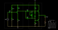
I´m trying, for educational purposes, to mount a little audio amplifier, joining a class A amplifier to amplify the voltage of a signal (from a smartphone) and using a class ab amplifier to gain power and move a speaker.
I create a simulation using Falstad.com/circuit simulator (you can see it here)
Questions:
The initial specifications are:
I´m trying, for educational purposes, to mount a little audio amplifier, joining a class A amplifier to amplify the voltage of a signal (from a smartphone) and using a class ab amplifier to gain power and move a speaker.
I create a simulation using Falstad.com/circuit simulator (you can see it here)
Questions:
- How can I elevate the input impedance of the class ab amplifier?? I think that this is the problem that makes the system doesn´t work at all... As you see in the simulation when I join the two amplifiers the output voltage of the first one falls absolutely...
- It would be better include some emitter resistors in the class ab amplifier? I think that it could help me to mantain the stability
- How can I calculate the output capacitor? I know that it has to charge during the first part of the signal, but i didn´t find information about how to calculate it.
The initial specifications are:
- Speaker power: 2Wrms
- Source voltage: 12V
- Smartphone output signal: 4Vp (we will use a potentiometer before the first amp to regulate the amount of signal).
- Smartphone Output impedande: about 400 Ohmns.
Attachments
-
 43.5 KB Views: 38


