Facebook
 Google
 GitHub
 Linkedin
Hi:
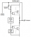
Attached is a sim for a Class AB amplifier with a single 40 volt supply. I get it that
Vcc / 2 = 40V / 2 = 20V output is not a realistic expectation. However, is an 11.7V
peak output realstic? How would a person estimate the real output?
David
Attached is a sim for a Class AB amplifier with a single 40 volt supply. I get it that
Vcc / 2 = 40V / 2 = 20V output is not a realistic expectation. However, is an 11.7V
peak output realstic? How would a person estimate the real output?
David
Attachments
-
2.9 KB Views: 49