How do you calculate for coupling capacitors for common emitter multistage amplifiers? And what does the input impedance of the common emitter amplifiers have to do with it?
How do you calculate for coupling capacitors for common emitter multistage amplifiers? And what does the input impedance of the common emitter amplifiers have to do with it?
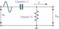
The purpose of an inter-stage coupling capacitor is to block DC from reaching the input of the following stage.
It constitutes a high-pass filter, i.e. low frequencies are attenuated.
What you need to determine is the low frequency cut-off point you are willing to accept. Look up RC high-pass filter to determine the cut-off frequency. When in doubt, you can go with higher capacitance rather than lower capacitance.
a too large coupling capacitor may induce temporal clipping or a very-low frequency "square wave" excursion of the output
especially at frequency jump points so it is better to keep as low as possible for wideband signal
a too large coupling capacitor may induce temporal clipping or a very-low frequency "square wave" excursion of the output
especially at frequency jump points so it is better to keep as low as possible for wideband signal
How do you calculate for coupling capacitors for common emitter multistage amplifiers? And what does the input impedance of the common emitter amplifiers have to do with it?
The lower cutoff frequency wo for the highpass (start of the passband) is determined by the coupling capacitor Cs and the corresponding resistor Reff which is responsible for charging/discharging of Cs.
The effective time constant is T=Reff*Cs with wo=1/T
This resistor Reff involves the internal resistance of the driving signal source Ro as well as the input resistance of the amplifying device rin (dynamic quantity)
The lower cutoff frequency wo for the highpass (start of the passband) is determined by the coupling capacitor Cs and the corresponding resistor Reff which is responsible for charging/discharging of Cs.
The effective time constant is T=Reff*Cs with wo=1/T
This resistor Reff involves the internal resistance of the driving signal source Ro as well as the input resistance of the amplifying device rin (dynamic quantity)
The purpose of an inter-stage coupling capacitor is to block DC from reaching the input of the following stage.
It constitutes a high-pass filter, i.e. low frequencies are attenuated.
What you need to determine is the low frequency cut-off point you are willing to accept. Look up RC high-pass filter to determine the cut-off frequency. When in doubt, you can go with higher capacitance rather than lower capacitance.
a too large coupling capacitor may induce temporal clipping or a very-low frequency "square wave" excursion of the output
especially at frequency jump points so it is better to keep as low as possible for wideband signal
a too large coupling capacitor may induce temporal clipping or a very-low frequency "square wave" excursion of the output
especially at frequency jump points so it is better to keep as low as possible for wideband signal
Thank you for your help yeah I know about this temporal clipping about the two large coupling capacitance. Thank you for the response and this brings up another question, would you please tell me what are frequency jump points?
Thank you for your help yeah I know about this temporal clipping about the two large coupling capacitance. Thank you for the response and this brings up another question, would you please tell me what are frequency jump points?
I had just found something out about it going into oscillations and unexpectedly signals drifting out of phase....?? I got a lot to learn about this I have come across these issues
Parasitic capacitance values are usually very small, in pF ranges and can affect RF applications. They are negligible for audio frequency applications.
I had just found something out about it going into oscillations and unexpectedly signals drifting out of phase....?? I got a lot to learn about this I have come across these issues
The math and physics of inductors and capacitors reveal that they inherently introduce phase shifts. Thus all filters using inductors and capacitors show phase shifts.
Let us examine the performance of a simple RC high pass filter.
To keep it simple, I have chosen a cut-off frequency of 1kHz and C is 1μF.
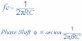
For this to happen, R is calculated to be 159Ω using the formulas,
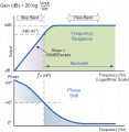
While ignoring the math, let us analyse what happens over the entire frequency range.
Since this is a high-pass filter, at very high frequency, the impedance (reactance) of C is almost zero. The sine wave propagates through with no change.
At very low frequencies, down to DC, the impedance of C is very large. The sine wave is blocked. The output amplitude is zero. The nature of the capacitance introduces a 90° phase shift if any minuscule signal manages to pass through.
It gets interesting at the critical turning point called the cut-off frequency fc. At this point, the reactance of C is the same as the reactance (resistance) of R.
The reactance of C is given as:
Xc = 1/(2πfC)
At f = 1kHz
Xc = 159 Ω
in other words, Xc = R at the cut-off frequency fc.
If you look at the RC high-pass circuit again, C and R constitute a voltage divider. When Xc = R, the voltage gain is 0.707 or -3dB.
As for phase shift, we went from one extreme of 0° to the other extreme of 90° phase-shift.
At the cut-off frequency, we see a phase-shift of 45°.
Take away: all frequency filters have phase shifts.
..................................
This resistor Reff involves the internal resistance of the driving signal source Ro as well as the input resistance of the amplifying device rin (dynamic quantity)
What remains is to know if both resistances forming Reff are to be considered in series or in parallel.
For an answer, the easiest way is to consider the discharging process for the capacitor (resp. the corresponding current).
You only have to ask yourself: Which resistor combination is seen by the capacitor during discharging?
well it has occurred 2-ce or 3-ce with huge gain or at upper banwidth of the transistor
the point is that the BE junction is a diode that will act sort of as a current pump (nonlinear)
means - your working point varies with frequency
if there is relatively large change at frequency - the working point needs to adjust a considerable step which (while running near the capabilities of the amplification stage) would distort the DC bias of the output temporarily
((if there is no willing to understand things - it does not matter how well something is described))
It sounds like he is talking about limiting the signal to prevent input saturation, but we don't usually do that through the choice of input coupling capacitor.

 Facebook
 Google
 GitHub
 Linkedin