Count down timer for my soccer club

Thread Starter

chrischrischris

Joined Feb 18, 2012
317
Bill, the article "Meter check of transistor" - brilliant.
I now confidently labelled all my transistors, know if they are CBE or ECB, noted all their hFE values (from data sheets) and now know how to check a transistor for faults. Thankyou.

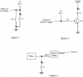
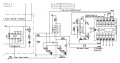
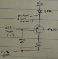
I now what to check I've installed my transistors the right way in my circuits, as well as check I've used the correct base resistors. Could you please check the following 3 questions:

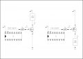
1. If the diagrams below are drawn correctly (setup)?
2. When calculating the base resistor, do I use the Hfe (min) or Hfe (max)?
3. "As an example", are my calculations below correct:

Given:
Vcc=24V
Ic = 75mA (5 leds in parrallel at 15mA each - appropriate resistor included)
Transistor used = BC547
hFE = 110 (min) and 800 (max)
transistor Ic (max) rating = 100mA (therefore suitable for the LED load)

then,
if hFE=Ic/Ib (and Ic=75mA, hFE=110)
Ib=Ic/hFE = 75/110 = 0.68mA

so,
If ICv = 12V and Ib = 0.68mA,
R=V/I = 12/0.00068 = 17,650Ω.
For full saturation, then maybe use a 10KΩ or 15KΩ resistor.

Is this correct?
 

Attachments

Wendy

Joined Mar 24, 2008
23,797
I can not spend as much time as I would like, so I will come back to this when I have more time.

The second drawing is a non starter, there is no condition where current does not flow through the base, so it will not work, it is why I came up with the other configuration on example 2. When there is no current through the BE on Q1 it will turn off.


Here is your drawing, redrawn.


Attachments

Thread Starter

chrischrischris

Joined Feb 18, 2012
317
In the first illustration, I meant to ask if this is the setup (NPN) for a signal that changes from low to high on an IC - turning on a load when a signal goes high. Load on the high end of the circuit.

In the second illustration, I though this was the setup (i.e. a PNP) for a signal that changes from high to low on an IC - turning on a load when the signal goes low. Load on the low end of the circuit.

Isn't what you've drawn in a darlington pair? I'm really looking to see how to turn on a load with a bipolar transistor (load on which side) and different between PNP and NPN. Also then how to do the calculations.

I'm looking at your setup in post #284. It show the load on the low end of the circuit for an NPN, whereas I see on the net when using an NPN as a switch it's on the high end. They also say a PNP is the reverse - load on the low side. If a little confused.
 

Wendy

Joined Mar 24, 2008
23,797
Part of the problem is you are confused as to the current path. Current enters the base and exits the emitter. This in turn controls the current entering the collector and exiting the emitter. I'm not sure I am competent to explain why this is so, it has been a long day. It is basic to transistor theory though. Think of a transistor where the BE is a control knob, adjusting the resistance between the CE.

A Darlington transistor looks like a conventional transistor with some differences. In most ways you treat a Darlington pair as one transistor (allowing for the differences). It multiplies the gain of both transistors (which is why I keep referring to it as a super gain transistor). The Base-Emitter junction drops around 1.3VDC instead of the normal 0.65 (I usually round this to 0.6VDC, most text books to 0.7). When fully on a conventional transistor can get very close to 0 volts on the Collector-Emitter, while a Darlington will drop 0.6V between the Collector-Emitter, which usually causes unwanted heating. The lower the voltage, the less power in heating generated (P=VI).

The high gain offsets the disadvantages in many cases. There are other transistor look alike configurations that also have high gain, but I don't want to confuse the issue at the moment. They also drop 0.6 volts Collector-Emitter, and Darlington can be bought pre-packaged, which is why they have been preferred.

Look at the current flows. On your second drawing you can never get the voltage, and therefore the current, to 0V between the Base-Emitter. It can not work because of this, in either state of the gate there will be substantial current flowing. I am going to show you another project where I had a different problem, but you should recognize the solution.

CMOS 555 Long Duration Red LED Flasher

The transistor polarities are reversed, but the principle is the same. I did this because this chip has a strong drive out the plus power supply, and very weak drive out the negative drive. The reasons I did it are different than why I did yours, but in many cases a solution can be applied more than one way in electronics. In many cases the same circuit is called a different name and the theory of operation is changed. It is all about perception.

If you would like to discuss transistor theory a bit off this thread I would be happy to do so, it can be very interesting. It is what got me hooked. :D I have probably missed several of your questions. If so make me repeat as necessary until I get it right.
 
Last edited:

Thread Starter

chrischrischris

Joined Feb 18, 2012
317
"Que Paso".....
"Yo no hablo espanol".
That's the only spanish I know - translation - I don't speak Spanish.:)
(though I know que paso)....

Sorry for the slow reply.
I did read your reply, just haven't had the time to sit and study it yet. In the meanwhile I've been trying to balance my PWM circuit as the new was working in reverse, but I think I got it now. I've also now found the score is not counting correctly when the digits are on full brightness. I believe it is debouncing. I'll check it on Sunday when I've got free time, and post the existing compared to my suggestion. It's almost 1am now - big soccer day tomorrow with end of season presentation. Talk more Sunday if ok.
More discussion on transistor - yes please - I've still got lots to learn.
 
Last edited:

Thread Starter

chrischrischris

Joined Feb 18, 2012
317
Actually, what the heck. Who needs sleep....
I've attached a copy of a typical mistake I think I've got in a few places.

Just to re-cap...
  • Most of my circuits are now being run by 12V.
  • I'm advancing say the score by using a transmitter/receiver setup
  • The receiver is made up of 12 relays powered by a 12V supply
  • Each relays have a NO and NC connection
  • By pressing a button on my remote it changes the relay to NC which feeds a pulse of 12V to the circuit to say make the score go up by a value of 1.

Problem:
I think it's bouncing and drawing too much current. Also the current may be peaking (momentary high current spike) which may eventually burn out the relay. The steady current I measure however when the button is being held on is 11mA going to the base of the transistors.

The images below are before and after - for just one typical occurance of this setup:

Old.jpg New.jpg

With 12V coming from R1 (receiver relay 1), I think I need to put say a 1KΩ resistor between it and the base, and increase the existing 1KΩ I have currently drawn there to say 10K. This ends up around a little under 11V? to the emmitter of the NPN feeding the signal to the 4518. I'm also guessing that when the 0.1uF is not charged, pressing the remote that feeds 12V to the base of the transistor causes a momentary dead short until the cap charges. This is the the high spike that I'm guessing may eventually burn out the relay.
 
Last edited:

elec_mech

Joined Nov 12, 2008
1,500
I did read your reply, just haven't had the time to sit and study it yet
Okay, I've finally had some time to catch up and learned a little studying Bill's responses. If it helps, here's what I understand from Bill on the subject of your NPN and PNP circuits,

Key statements:

Current enters the base and exits the emitter. This in turn controls the current entering the collector and exiting the emitter.
Look at the current flows. On your second drawing you can never get the voltage, and therefore the current, to 0V between the Base-Emitter
The NPN circuit will work because the voltage on the emitter is 0V at all times because it is tied to ground. When the voltage from pin 15 to the base is low, i.e., 0V, then the base is 0V and the emitter is 0V and therefore the difference between the base and emitter voltages, Vbe, is 0V, which will turn the transistor off.

The PNP circuit will not work for the same reason. The emitter in this circuit is tied to 24VDC, therefore the emitter voltage will always be 24VDC. When pin 15 is high, i.e., 12VDC, the base will be 12VDC. The difference between the base and emitter voltages will be 24-12 = 12VDC. Because the base to emitter voltage is 12VDC and not 0V, the transistor will never turn off.

It took me reading and studying this several times before I saw this. Bill already said this, I just put it another way that makes more sense to me in the hopes it helps someone.

BTW Bill, I, too, would be very interested in learning more about transistor theory. That little bit above has eluded me for a while and finally makes sense. Perhaps you can add transistor theory to your blog sometime? Just please let me know if/when you do be it blog or some other form. Again, someday I'd love to put together an ABC cookbook that gets to the meat and potatoes of key things and explains things simply through various examples.

Ever onward. Okay Chris, how do you know the following to be true or what makes you think this is happening:

I think it's bouncing and drawing too much current. Also the current may be peaking (momentary high current spike) which may eventually burn out the relay.


Looking at your circuit, a few notes:
  1. Why the transistor? The CMOS IC won't draw much current. Is it being used as a buffer or isolator of sorts from the receiver?
  2. Note the count indicator LED may be allowing pin 1 of the 4518 to float, I'm not positive though. I'd suggest using a 10kΩ pulldown resistor on pin 1 and putting the LED and LED resistor in parallel with the 10kΩ. In this way you've got a direct connection to ground. If the LED is impeding the ground connection to pin 1 when off, then you're left with a floating ground which may contribute to your bouncing digit problem.
  3. How does the relay work? You press a button on the remote and the relay closes, allowing 12V to go to the transistor base. Does the relay stay closed for as long as you hold the button, does it open after a second or two, or does it stay closed until the button is pressed again? This will impact what you need to add to the output of the relay.
  4. If you want to be safe and charge ahead, I'd suggest using the transistor to power the count indicator LED only and use a CD4093 Schmitt trigger IC with a 10kΩ resistor and a 0.1uF capacitor. Tie all unused INPUTs to ground. When the relay closes, be it for a second or indefinitely, the Schmitt trigger will send a quick pulse to the output, giving you a nice, clean, single clock signal. I can post a schematic if you'd like.
I'm in China on business and gotta run to dinner, otherwise I'd love to chat.
 

Thread Starter

chrischrischris

Joined Feb 18, 2012
317
I see what you're saying about the PNP. I suppose I need to see how it get's wired up then to switch.


  1. The reason for the transistor/resistor/capacitor setup was because I saw it in another design on the net. The design was setup as a "debounce" trigger method.
    http://members.shaw.ca/roma/one%20digit.html
  2. I tried to put a 10K between pin 1 and gnd. Unfortunately it didn't correct the problem. Not sure what you meant by parallel to the LED and 10K - I couldn't see how else to do it.
  3. The relays are NO. As I press and hold a button on the remote, the relay stays NC until I let go of the button. It's odd that with different voltages, resistors & capacitors, the count accuracy and debounce changes. I'm wondering if I'm just missing the correct calculated values???
  4. Maybe I should bite the bullet and just insert a CD4093 on the existing board. I was just hoping I could get away with not doing that. If you could show me how to wire it into the existing diagram, that would be good to have as a plan B. I'd need to wire it up for the "home" count score and also for the "away" count score.
What current do the ICs draw? If any were fed directly from a relay, or feeding the relay, what current would be present?

I'll attached all circuits to date below (except the clock). I've been adding more details to the diagrams. The currents noted on the first diagram were based on the older transistor setup show in the previous note.
Circuit 1.jpg Circuit 2.jpg Circuit 3.jpg Circuit 4.jpg Circuit 5.jpg Circuit 6.jpg

So are you on work at China?
 
Last edited:

Wendy

Joined Mar 24, 2008
23,797
OK, I have a few hours to spend here. About your schematics, I can not fault them except in one way, which I am about to explain. They do exactly what I would want them to do as a tech, but I can not read the function of a circuit from the top view of the chips, so the first order of business is add the functional diagram (and insert it into my PaintCAD, which is how it grows its library).

Then I can actually look at the circuit and actually understand it. Many times things will jump out that didn't before.

We start with the functional diagram found in the data sheet, and translate it over. So here is my starting point...


You just responded to my message, so I'll see you in the chat room.

http://xat.com/All_about_circuits
 

Attachments

elec_mech

Joined Nov 12, 2008
1,500
The reason for the transistor/resistor/capacitor setup was because I saw it in another design on the net. The design was setup as a "debounce" trigger method.
Hmm, at a glance, I didn't see an explanation for the transistor debounce portion, specifically how it worked. We'll see what Bill's thoughts are. It may well be fine - test it by removing the indicator LED but keeping the 5kΩ resistor connected to ground. I think the LED is preventing a true ground connection which may result in the bounce you're seeing.

I tried to put a 10K between pin 1 and gnd. Unfortunately it didn't correct the problem. Not sure what you meant by parallel to the LED and 10K - I couldn't see how else to do it.
I've attached a hastily drawn couple of options for connecting to pin 1.

The relays are NO. As I press and hold a button on the remote, the relay stays NC until I let go of the button. It's odd that with different voltages, resistors & capacitors, the count accuracy and debounce changes. I'm wondering if I'm just missing the correct calculated values???
Excellent, so the relay is acting exactly like a mechanical switch. Different resistor and capacitor values will give you different delay times. I think the Schmitt trigger will help eliminate a lot of this experimenting.

Maybe I should bite the bullet and just insert a CD4093 on the existing board. I was just hoping I could get away with not doing that. If you could show me how to wire it into the existing diagram, that would be good to have as a plan B. I'd need to wire it up for the "home" count score and also for the "away" count score.
The CD4093 will give you four debounce inputs and outputs. See attachments.

What current do the ICs draw? If any were fed directly from a relay, or feeding the relay, what current would be present?
I don't know offhand, but the datasheets will tell you. Look for I input for low and high. I can't imagine it's much.

I'll try to look over your schematics when time allows. Yup, in China on business visiting a supplier. In many ways, very different from the U.S., in others, not so much. I do miss my meat and potatoes (not to mention wife and child). :)
 

Attachments

Wendy

Joined Mar 24, 2008
23,797
Chris and I have been chatting. The chat room is not closed, it is there for all to use. It has a nice doodle screen (think digital chalkboard) to use.

My starter debounce schematics start here. The inverter is a 555.


When feeding from relay circuit you need to move the resistor to the output of the relay, the idea is to slow the switch bounces down.

Here is a cleaned up drawing of the picture we used on the doodle screen.


Attachments

Last edited:

elec_mech

Joined Nov 12, 2008
1,500
The chat room is not closed, it is there for all to use.
I haven't tried using chat before, but it wasn't that I didn't want to join you so much as I'm 12 hours ahead of EST and I had to head to bed right after my last post. Between meals and working, the days are very long for me right now, so I pop in when I can and try to get a reasonable amount of sleep. ;)

The inverter is a 555.
So the 555 is being used as an inverted output Schmitt trigger? Cool beans. I like the CD4093 as a Schmitt trigger because it only requires two parts per input and you can get four I/Os in a smaller footprint.

Okay, I see two different circuits in your last post. The first uses a Schmitt trigger which I understand. The second uses a similar transistor circuit to the one the OP posted earlier. Is the transistor acting as a Schmitt trigger or serving some other debounce function? How do you keep the base pulled low when the relay is open?
 

Thread Starter

chrischrischris

Joined Feb 18, 2012
317
Bill, unfortunately the circuit didn't fix the bouncing.

I was about to try the schmitt trigger instead with the 4093, but just before doing so I noticed that elec_mech pointed out lack of grounding the base when the relay was open.

I added a 100KΩ from the base to ground. The trigger stopped bouncing. I changed it to 10KΩ - still good. Is this correct? If so, what value should I use? See picture below

debouncing.jpg
 
Last edited:

Thread Starter

chrischrischris

Joined Feb 18, 2012
317
One thing I would have liked to have done, that doesn't seem to work anymore is pausing the count down timer when I hit the reset button.


How this currently works:
  • If however relay button 5 is pressed at any time, it pauses the count. This is achieved by the use of a 555 flip flop latch setup. Relay 5 controlled by the remote flips the 555 flip flop to cause pin 3 to hold high which in turn is connected directly to the reset pin of the 4027 JK flip flop. The 1 Hz timing signal therefore pauses
  • Pressing button 5 again, flips the 555 latch pin 3 to low, which no longer holds pin 4 reset of the 4027 high, hence it starts to tick again.t
  • If relay button 11 is pressed, this pulses a signal to pin 2 of a 555 that acts as a monostable timer giving 12V to the common of relays 9, 10, 11 and 12 for a timed duration of 30 seconds only
  • The reason for the timer is as a safety. It allows a timed window for the operator to either resets the count down timer (button 12), or, change the clock time (separate circuit) via fast advance (button 9) or slow advance (button 10).
  • The pressing of relay button 12 sends a 12V pulse to 2 places:
    • To the 4510 up down counters to reset to a preset time (say 45:00). With the diode setup and the 4017 decade counter pressing relay button 12 repeatedly toggles through different preset times
    • To the 555 latch flip flop. This pauses the count again via the 4027

What doesn't happen however, is when I press pin 12 to reset and pause, only reset works but the clock keeps counting down. Can anyone spot the mistake?
 

Attachments

Last edited:

elec_mech

Joined Nov 12, 2008
1,500
Okay, I'm seeing a few things I'd suggest making changes to or have questions on:
  1. In addition to a 0.1uF, there should also be an electrolytic capacitor between Vcc and GND as close to each 555 as possible. A 1uF would be fine. I can't immediately recall why, but SgtWookie had mentioned this in a post I read sometime ago.
  2. How does relay R5 work? One end of the relay goes to pin 2 of the toggle 555 which makes sense, but I'd expect the other end of the relay to be connected to Vcc, but it is connected between a 100kΩ and a 0.1uF coming off pin 3.
  3. Ah, I think I see the problem now. The output of relay 12 is connected directly to the flip flop, more or less. I suspect if you hold down the switch controlling relay 12, you'll see the timer pause for as long as you hold the switch down, then it will resume as soon as you release the switch.
How do you want the pause feature to work with the preset function? You press button 12 once, the count resets to 45:00 and stops? Then each subsequent press of 12 resets the count to another number while the count stays paused? Then the count stays paused until button 5 is pressed?

Hmm, if my description above is correct, my first inclination is to connect the output of relay 12 to pin 2 of the toggle 555, but if you press 12 again to change the preset time, the timer would start again. Sounds like you need to have the count paused the first time 12 is pressed as long as the output of the 555 30-second timer is high.

I don't have time to do a nice schematic, but I quickly sketched something, took a picture and attached it. I've never used an SCR before, but as I understand their operation, once tripped, they maintain a latch until the circuit they are powering is "opened". The sketch is a concept only. Once 11 is pressed and 12 has power, the first time 12 is pressed, power goes to the SCR causing it to latch. There is a PNP transistor in-line with the SCR controlled by the output of the toggle 555. If the toggle output is low (off), the PNP will be on and the clock reset pin will go and remain high until button 5 is pressed and the toggle 555 goes high. Ugh, of course I just realized this forces the user to press 5 twice to turn on the clock again. I'm sure there is a workaround, this is just a possible solution. Hopefully Bill will see an even simplier solution. Gotta book - I'll try to give it some more thought in the meantime.
 

Attachments

Thread Starter

chrischrischris

Joined Feb 18, 2012
317
Okay, I'm seeing a few things I'd suggest making changes...there should also be an electrolytic capacitor between Vcc and GND as close to each 555 as possible
Will do.

How does relay R5 work?
I adapted a circuit I found on the next for a flip flop latch circuit:

http://www.electronics-lab.com/projects/misc/012/Schematic.png

I suspect if you hold down the switch controlling relay 12, you'll see the timer pause for as long as you hold the switch down, then it will resume as soon as you release the switch
I just tested that and found it sort of does works.
If I power up the timer with button 11, then just quickly press button 12 to reset and pause, it resets only but keeps counting down.

If however I hold down button 12 for at least 1 second, I can see the LED indicator light go from dim to bright as it "latches" the pause. It simply has to be held down longer than a second. I have no idea why. So the problem here is to get it to latch faster.

How do you want the pause feature to work with the preset function? You press button 12 once, the count resets to 45:00 and stops? Then each subsequent press of 12 resets the count to another number while the count stays paused? Then the count stays paused until button 5 is pressed?
Exactly correct.

Any suggestions to speeding up the latch?
 
Last edited:

elec_mech

Joined Nov 12, 2008
1,500
I adapted a circuit I found on the next for a flip flop latch circuit:

[URL]http://www.electronics-lab.com/proje.../Schematic.png[/URL]
Ah, I got it now.

If however I hold down button 12 for at least 1 second, I can see the LED indicator light go from dim to bright as it "latches" the pause. It simply has to be held down longer than a second. I have no idea why. So the problem here is to get it to latch faster.
Based on your last schematic, I can't "see" how the clock pause function gets "latched" once relay 12 is open. So it stays latched if you hold relay 12 closed for more than a second?

I'll post a modified schematic when I can get to a better internet connection later tonight.
 

Thread Starter

chrischrischris

Joined Feb 18, 2012
317
Yes, the pause does stay latched if hold relay closed longer than 1 second. Not sure how.
I just found that if I parallel a 10K across the existing 10K (i.e. ended up 5K) from pin 2 of the 555 to ground, the circuit would not unlatch.
I then added a 100K in parallel with the 10K (resultant 9K) and it would latch / unlatch well. So there must be a calculated value that is "correct"???

As for the score counter - damn, after all that excitement - still not working smoothly...

Next.jpg

It counts all over the place. I tried changing the cap from 0.01F all the way through to 1uF. It seemed to affect it a little - different results - but none clean. I'm pulling my hair out here.

Hang on, I just placed a 0.47uF from pin 15 of the 4518 and gnd and it seems to be better. Also tried 1uF - same. Only "very occassionally" does it skip a beat and count up by 2 rather than the usual 1. Sometimes however it jumps by even higher values. Any ideas why?
 
Last edited:
Top