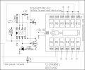
Can someone please have a look at the attached circuit and see why the CD4027 gets fairly warm. The 555 operating the "reset time delay" also gets warm when activated and timing.
Your 4027 is driving a LED directly. If you look at the design you got the time base from you will find a transistor is used to drive my design, this is to prevent loading the chip exactly the way you have, they are not designed to do this. CMOS in general are fairly fragile, they work great if you follow the rules, and I love going outside the rules, but when it matters you have to be very conservative.
I'll study it some more. Just printed out the schematic.
Thanks Bill.
As I was driving into work today I was wondering if it was the LEDs that I added to my circuit boards that have been causing me all the problems. I was "guessing" to use transistors - just hadn't tried it yet. Thanks for confirming.
Interesting that now that I've increased the driving voltage of my circuits from 5V to 12V there has been quite a few abnormalities appearing. My scores have not been increasing in a regular fashion but a bit all over the place. The count-down timer when re-set has been jumping around at random. My clock when forwarded to change the time "flies" at a zillion miles an hour.
0.1uF capactors - they seem to fix a multitude of sins - trial and error in my case.
I did find however that most of my problems were around the "LEDs" that I added. So reply confirms my suspicions. Ta.
No, a common collector, which is shown in my design, will draw through the base-emitter the current through the emitter divided by the β of the transistor. It is possible you have other current paths I haven't spotted yet. I am up because I have trouble sleeping during the day.
You will note on my design I go for very high values, CMOS is many, many megohms input resistance (actually much more) and a few hundred ohms output resistance. The catch is it has absolutely no drive to speak of at all.
So if you have an LED and transistor arrangement, with 10ma going through the collector emitter and the gain is 50, you would have around 0.2ma through the base (or 200µa). A super gain transistor drops 1.2V on the BE, but draws substantially less current.
I have a standard illustration in my library of electronics just for this...
In this design the resistor/LED will drop the input voltage of the base of the transistor minus the 0.6VDC drop of the base-emitter. I use this a lot.
Bill, I found where the heat in the 4027 was coming from.
I got a spare socket, soldered wires to each of the 16 legs, put the IC on this new socket and each wire to the socket on the board. Then I started pulling out all the ones that were going to ground.
I found that when I pulled out 15, it cooled down. 15 is Q1 which gives out a 0.5hz signal (that I wasn't using). I also grounded pin 14 - q1. Since I'm not using that side of the IC, I disconnected pins 13, 14 & 15(clock1).
I had originally grounded it because at one stage elec_mech suggested I ground all unused inputs in CMOS ICs. I "assumed" these were inputs. Oops. Problem now solved.
I had originally grounded it because at one stage elec_mech suggested I ground all unused inputs in CMOS ICs. I "assumed" these were inputs. Oops. Problem now solved.
Sorry I haven't had as much time as I'd like lately to look this over. On the CD4027, since you're not using the first J-K flip flop, ground pins 9-13. Leave pins 14 and 15 unconnected. Disconnect pin 2 from ground and leave unconnected. Disconnect pin 1 from pin 13.
Is the 555 still getting hot? If you remove the LEDs, does it still get hot?
Are you still having issues with the display going crazy if reset is activated? I assume by this you mean that instead of going to zero, the display picks a number at random and holds it there. Is that correct or is something else happening?
How about the "flying time" and scores not increasing as expected?
Hi elec_mech.
Suggestions on the 4027 - I thought that was the case. I am only using one of the 2 flip flops, so your suggestions make perfect sense. I'll make the mods tomorrow.
As for the 555's, yes they are getting a "little" warm. Nothing excessive however. It's just I'm a little paranoid as all the other components are dead cold. I think the 555 is getting a bit warm with the LED - again I'll check again tomorrow (disconnect and see the result).
As for the random displays, I found that this was being caused when I pressed a button on the remote control that signalled the receiver, that gave a pulse to one of the circuits. Placing a 0.1uF across ground and each of these receiver relays outputs seemed each time to fix the problem. A well placed capacitor seems to make a world of difference. So they are all now working smoothly now.
Next - making the "dots" for the time (i.e. 45:00). Then I'll adjust the PWM for the correct light intensity. I then want to still see if I can tap off the 24V and with the 12V voltage regulator I breadboarded (via an LM317) if I can run the circuits (without numbers jumping). I'll let you now if there are any problems.
Bill, I took your advice and added a BC547 to drive the LED on the circuit.
Elec_mech, I also took your advice and checked to temperature of the 555's. I added a transistor between each of the LEDs on one of the 555s. Heat's gone. However, on the other 555 adding a transistor didn't remove the heat. The heat however is ever so slight - maybe not worth worrying about:
Can someone please tell me if the pins on a 2N2222 are CBE from left to right when facing the flat face and pins pointing down? Is this the case for all NPNs? (and the opposite for PNPs).
If I google 2N2222, some diagrams show left to right as CBE and others EBC. Which is it? Why are the diagrams different?
Unless Bill disagrees, I'd add a base resistor between the 555 and the transistor. This might help with the heat. Right now you're feeding it all the current the 555 can provide (potentially).
I'm trying to look up a simple test you can perform to determine which pin is which on a transistor. I cheat and use a transistor checker from RadioShack I bought many years ago.
Does your meter have a transistor checker on it? It would have 3 or 6 (NPN and PNP) holes for transistors. From what I'm reading, you put the base lead in the base hole and put the other two in one orientation and check the hfe value. Turn the transistor around (base in same hole, other two pins in opposite holes from before) and measure the hfe again. The higher hfe value corresponds to the correct orientation as labeled on the holes. I'd check your meter manual to be safe. Info I found: http://www.edaboard.com/thread106051.html, post #8 specifically.
Where did you purchase them? If at an online components distributor, then they should have the correct datasheet posted. Alternately, search for the datasheet of the specific manufacturer and whole part number on the transistor. Take a clear picture of the transistor and we can help too.
I pointed out the 2N2222, however it would account also for others - BC547, 2907, etc.
From literature I've read, it seems that both NPN and PNP are CBE from left to right (flat facing, and pins down). Maybe someone just has got the pictures mixed up.
This is where I'm getting confused. Is there a convention for reading CBE from left to right for a NPN and EBC for a PNP also reading from left to right? Above in the NPN I can see it's either way. Why don't they put a "dot" or something to indicate say "C"?
 Facebook
 Google
 GitHub
 Linkedin