Count down timer for my soccer club

Thread Starter

chrischrischris

Joined Feb 18, 2012
317
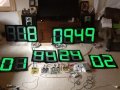
I've just connected 8 of the 15 digits:
"Away" score = 2 digits + "Home" score = 2 digits + countdown timer = 4 digits. I've connected these via the PWM circuit.
The digits work perfectly - the off digits are not dim - they're off.

Only problem at the moment is that my timer doesn't reset to all numbers. When I reset it, it should toggle through the times 45 minutes, then 40, 35, 30, 25 and back to 45 again. It seems however to jump around in different orders. I'm guessing its something to do with the reset being triggering more than once with a single press of my remote control. I'll have to look into it later.

As far the mosfet, it's warm to touch. When on full brightness (with 8 out of 15 digits working so far) it's quite warm, but still holdable in my finger tips. The heatsink will dissipate the temperature, but is it ok running that hot (when I have 15)? Should I run the current through 2 of these mosfets in parallel? or is that even possible?

Post edited:
Just found out the problem with countdown not resetting properly. I'm running all the circuits now at 5V. At this voltage, the countdown timer jumps. I increased to 6.5V and it works perfectly. However then I found the score jumped up by 2's instead of 1's. I can't win!!!
 
Last edited:

Wendy

Joined Mar 24, 2008
23,797
You may need to slow some of the pulses down with a simple RC filter, say around 100Ω and 100pf. It will eliminate transients.

I've been thinking about the other problem, I can cure it, but it will take more circuitry. Basically you are having timing problems from the DAC chip you are using and the fact it is trying to multiplex the digits, it isn't the dimmer per se. A latch and hold to eliminate any timing issues would fix this, but like I said, more circuitry. Interested?

I could be wrong, but it is my interpretation of what is happening.
 
Last edited:

Thread Starter

chrischrischris

Joined Feb 18, 2012
317
The RC filter - what problem do you mean this may eliminate? I'm not sure what you mean by it affecting the transients. Do you mean in the temperature digits displaying the off led very dimly, or the resetting of the countdown timer being temperamental? If the later, how do I wire this up.
 

Wendy

Joined Mar 24, 2008
23,797
I'm thinking of where it is counting twice. It sounds like two pulse where the should be one.

The dim LEDs are a different issue, I think.
 

Thread Starter

chrischrischris

Joined Feb 18, 2012
317
Tonight I've "neatened up" the PWM circuit.
I've also created three power supplies from the 24V supply using voltage regulators (LM317's). These are 5V, 9V and 12V.

I need 5V for the temperature circuit, 12V for the remote control unit and I'm going to experiment now to see if the 9V can be used for the other 3 circuits (as it was working when I made them in the first place). If things don't work, I'll then look at the RC filter.
 

Thread Starter

chrischrischris

Joined Feb 18, 2012
317
Bill, I've re-visited my circuits to check the various voltages I'm using:
  • Voltage to power digits 24V - that's set.
  • Currently the remote receiver is 12V. That's also not changeable
  • The temperature circuits needs +5V to -5V
  • The score, counter and clock I was running on 9V

Lately I've been trying everything on 5V just so I didn't have to have too many voltages. The reason I was originally running the 3 circuits on 9 volts was because I happened to have a 9V supply. I didn't alter this as I had sized up the correct resistors to run with the small 1 inch 7 segment displays I was testing with. However I'm now thinking I could use 12V instead....

I think the 4000 series ICs can run between 3V to 15V.
The ULN2003a's I think are rated at 30V
The 2N2222 and 2N2907 are rated at 60V
The 555 is rated at 16V

So maybe I just create 2 voltage regulators, namely 12V and 5V. In hind sight, I suppose I could have even built the 5V voltage regulator directly on the temperature circuit board (being fed 12V as well).

What are your thoughts?
 

Wendy

Joined Mar 24, 2008
23,797
Simplification is always good. The 5V on one board is also good. I frequently use 9V because of 9V batteries (which are usually 7V), but 12V is my preferred voltage. How close are you to making the big board do you think?
 

Thread Starter

chrischrischris

Joined Feb 18, 2012
317
I've designed the frame - around 3.6m x 2.4m high (12' x 8'). The digits are built. The circuits (except PWM and power) are built. The graphics for the sign is drawn. So I'm getting close.

I am going to try and simplify and setup via 12V only.
The PWM however therefore needs re-designing (resistor values).
If I do this, I have 2 questions:

1. Could you check the resistor and capacitor values as shown in post #203 need changing

2. With the resistors on the LDR setup (refer to your note of inverting the signal - post #231) can you check if my calculations are correct (amended diagram below):


Attachments

Last edited:

Wendy

Joined Mar 24, 2008
23,797
It should be symmetrical. The old setup was 1/3 and 1/2 Vcc, give or take. The new setup should be 2/3 and 1/2 Vcc. You should have been able to just move the resistors from one side to the other, which is how I'm defining symmetrical.
 

Wendy

Joined Mar 24, 2008
23,797
Unfortunately, yes. It is out old friend P = I X V at work, and 12V is a bit largish on drops. 0.1 Amps and 12V is over a watt. A really simple switcher will get rid of this heat, but if a heat sink keeps the linear regulator cool it is no big deal.

I can show you a switcher, though most of our members can show better (already on chips). I like my parts list simple, sometimes too much so.
 

Thread Starter

chrischrischris

Joined Feb 18, 2012
317
How did you calculate 0.1amp?

I found however that if I held the LM317 between my fingers, it kept cool. I'm not sure yet however if when I add all 3 circuits (rather than the current 2) if it will be much hotter. I'll measure the current.
 

Wendy

Joined Mar 24, 2008
23,797
It was by way of example, more amps is more extreme. If it is less, then it will be cooler. I pick values that seem reasonable and then mentally model it to see how the circuit might respond. If I have exact numbers I prefer to use them.

As you are finding it may not be a problem. I try to anticipate problems.

There is an old engineering saying.

Hope for the best, but plan for the worst.
 

Thread Starter

chrischrischris

Joined Feb 18, 2012
317
Bill, for your info, progress to date:
  • Digits no longer displaying dim when off - had something to do with power supplies. Earths all joined (though I thought they were before too)???
  • Had problem with the score jumping by 2's. Changed the 0.1uF capacitors to the base of transistors to pin 1 of the 4518's to 0.4uF. Now counting up correctly
  • Count down timer wasn't holding still when re-set - would start counting automatically. I changed a pull down resistor from pin 2 of one of the 555's from 10K to 6.8K - works well. With a pot I found the value had to be between 5.5 and 7.5. This was just trial and error!
  • LM317 voltage regulator to temperature display circuit - cools down easily with a small heat sink.
  • Current draw of other circuits (3) is around 250mA. Feeding via an LM317 voltage regulator makes it run too hot - needs a large heat sink, so I think I'll just stick to a dedicated 12V power supply (shame I can't use the 24V supply).
  • All looms made via 7 and 14 strand ribbon cable and IDC sockets
  • All circuits made except the PWM. That's next.
  • Have to still tweek the PWM voltage divider to get best light variation.
  • Still trying to work out why the temperature jumps from 60 to say 21 (Celsius) at random - when power turned on and off. Feels like interference somewhere. Probably another grounding issue.
Thanks for all your help to date. Getting much closer now.
 
Last edited:

Wendy

Joined Mar 24, 2008
23,797
A thought just occurred. You could make the thermometer and clock totally separate, as a public service. A time and temperature setup, if you will.
 

Thread Starter

chrischrischris

Joined Feb 18, 2012
317
The clock and temperature could have been a separate service. I did think about that. But I've now got it already designed in my circuit.

Also, I could have made the clock and temperature toggle from one to the other. That'll be another project down the track.

Bill, just going back to the 12V supply. I did measure the current the 3 circuits were drawing and found it was 250mA. Hence in the LM317 trail, it too would have been 250mA. These regulators are rated at 1.5A. However, when I connected the power via this unit, I held it with my fingers and couldn't keep it cool enough. Is it really only drawing 250mA? Because if so, why so hot? Would a heat sink fix the problem because it should handle 1.5A. Or am I measuring the current incorrectly through this unit? Would a big heat sink fix it?
 

Wendy

Joined Mar 24, 2008
23,797
Again, it is our old friend the power equation. You have your 24V a bit higher, as I recall. So the regulator is dropping 13V (25VDC - 12VDC).

0.25A X 13V = 3.25W

This is why people don't like analog power supplies, they are much purer, but there is a cost. You probably just need to put a much bigger heat sink (nowdays folks use fans, but for this project I wouldn't due to reliability.)

You can also get a LM317 in a TO3 case style, which is much, much beefier. The heat sinks that support TO3 case styles are also much beefier. It would be simpler than a SMPS regulator.

I can sketch one (SMPS regulator), but in my opinion it is overkill.

Regulators are simple, for now I would build this (the final unit) with a simple TO220 case style and a fan, with plans to replace it later. It would allow you to get the rest of the construction out of the way.
 
Top