Count down timer for my soccer club

Wendy

Joined Mar 24, 2008
23,797
Chris, today is my birthday, so it is going to be a busy day, but I will translate what you have into a schematic (I translated the 4518 into a gate print for PaintCAD). I suspect the base problem is simple. I am going to propose a few experiments when I get a chance to draw them too.

I know you did this a long time ago, but can you refer me to a link to the receiver specs again?
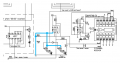
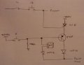
 

elec_mech

Joined Nov 12, 2008
1,500
Happy Birthday Bill!!!

Chris,

Something is not adding up. Please see attachment. Based on this schematic, I cannot see how the pause/resume LED or the one connected to relay 12 ever comes on. The collector of both transistors is tied to GND. Is this correct?

I just found that if I parallel a 10K across the existing 10K (i.e. ended up 5K) from pin 2 of the 555 to ground, the circuit would not unlatch.
I then added a 100K in parallel with the 10K (resultant 9K) and it would latch / unlatch well. So there must be a calculated value that is "correct"???
Okay, also confused here. I don't see how relay 12 affects operation of the 555 toggle. Is the latch/unlatch problem with relay 12 or relay 5? Could you verify the schematic is a match to your circuit under test?

If however I hold down button 12 for at least 1 second, I can see the LED indicator light go from dim to bright as it "latches" the pause.
Why is the LED dim and not off? Which LED, the one with PAUSE/RESUME written under it or the one to the left? The one on the left does not have a pulldown resistor on the base and really needs it. The one on the right is connected to pin 3 which will either output a low or high signal at all times, so it does not need a pulldown. Both transistors lack a base resistor - I'd suggest adding a 1kΩ to start with. I know you're keeping it simple and running it at full saturation, but I think a base resistor is almost always needed. Perhaps Bill can comment here.

I also can up with what I *think* is a workable solution to your relay 12 operation issue with pausing the clock. Please see the attachment. Again, I've never used an SCR, so I don't know if I'm missing anything or not. In theory, the first time relay 12 is on, the SCR is latched. A PNP transistor, which needs a base resistor I notice now, is pulled down by a 10kΩ resistor and also tied to the output of relay 5 which is normally disconnected (open). Therefore, the PNP transistor is normally on, so when the SCR is latched, the clock is paused. When later relay 5 is on, the base of the PNP transistor is pulled high and turns off for a moment, causing the SCR to unlatch. While this is done, the 555 is toggled, then relay 5 is open again, but since the SCR is no longer latched, it no longer pulls the clock reset high. Darn, of course, if the toggle has been off, it will be turned on again and the user will have to press 5 twice to get the clock going. Ugh, back to the drawing board . . .

As for the score counter - damn, after all that excitement - still not working smoothly...
One note about the schematic, you have the transistor labeled as NPN but it is drawn as a PNP.

I don't think adding a capacitor to pin 15 (reset) is going to address the problems you're having. In my limited reading on debouncing, CMOS ICs need a Schmitt trigger to truly give you the debounce you need. You can do this with a CD4093 or a 555. I'd suggest putting one on a breadboard and testing it on your circuit. I suspect this will solve your problem.

Let us know what you find out.
 

Attachments

Thread Starter

chrischrischris

Joined Feb 18, 2012
317
Something is not adding up. Please see attachment. Based on this schematic, I cannot see how the pause/resume LED or the one connected to relay 12 ever comes on. The collector of both transistors is tied to GND. Is this correct?
Yes, your right. The circuit is not draw correctly. The base of both NPNs are actuall both tied to Vcc.
Also, I noticed my circuit diagrams are drawn really badly and not labelled well. I've just corrected them, labelled and made them easier to read (see below):

Pause resume_2012-09-26.jpg

As far as operation, this is the best description I can give:
  1. When Relay 5 is pulsed, it flips IC1 pin 3 from high to low (and visa versa)
  2. This goes to the reset of IC 4027 (pin 4) which stops the count down (or makes it resume)
  3. This in turn either locks the "pause/resume LED indicator" on (or off)
  4. When relay 11 is pulsed, it momentarily connects pins 2 and 3 of IC2 (555) which flips pin 3 to high for a time of 30 seconds only. This then feeds 12V to the common of relays 9, 10 and 12 so that they become functional
  5. The reason for the timer is so that someone doesn't accidentally reset the count down timer during operation. They intentionally have to press 11 before 12 for the reset to work.
  6. This in switches on the "30 second Vcc LED indicator"
  7. When relay 12 is pulsed it:
    • Resets the time (via the 4510s and the preset time setup).
    • It also pulses the "reset LED indicator"
    • Through diode D1 it gives a high pulse to pin 3 of IC1 (555) which I think makes it flip on (if it's off)
    • This in turn switches the "pause/resume LED indicator"
    • If pin 3 is already high, it doesn't flip IC1 because it's already powered on
    • If relay 12 is pulsed repeatedly it toggles through different time settings with via the 4017 (10 output decade counter)

I think this is the logic. However as R1 is pulling pin 2 and pin 6 high and R2 is pulling it low at the same time, I think this is where there is a clash???

As for the score count, I will try the 4093 circuit on a breadboard as a test and see how it drives the scores.

Schmitt trigger:
Just tried it on a breadboard and it does work like a treat. Bit confused. In the circuit it's labelled as a 0.01uF, however in your notes you said to use 0.1uF. Also, the attachment showed the cap symbol with a line and arc - electolytic? If so, electrolytics don't come in 0.01uF.

I then tried both a 1uF electrolytic and ceramic - both worked equally well. Changed to a 10uF elec and I could only trigger every second or more. Tried 2x1uF ceramic - delay of about 1/3 second between presses. I assume I would have to size the cap to a value high enough to avoid advancing 2 numbers? Maybe a 3.3uF? Ceramic or elec?
 
Last edited:

Thread Starter

chrischrischris

Joined Feb 18, 2012
317
Elec_mech,
I ended up hacking my circuit board and installed the 4093 schmitt trigger. Score doesn't miss a beat now. I should have done that in the first place.

I still have a few questions:
1. The capacitors I used with the schmitt trigger - 3.3uF electrolytic (please read my previous post).
2. I left a pull down resistor on pins 1 and 15 of the 4518. Is this ok (refer attachment)
3. I'm still scratching my head about the reset/pause.

new score.jpg
 
Last edited:

Thread Starter

chrischrischris

Joined Feb 18, 2012
317
Elec_mech. I was wondering when you'd be on the travel again (going back from China). I guessed that's why the radio silence.
No problems. Whenever you have time.
 

elec_mech

Joined Nov 12, 2008
1,500
In the circuit it's labelled as a 0.01uF, however in your notes you said to use 0.1uF.
:eek: Oops, it is 0.01uF.

Also, the attachment showed the cap symbol with a line and arc - electolytic? If so, electrolytics don't come in 0.01uF.
Nope, just ceramic. I'm not positive, but an arc doesn't denote electrolytic, the presence of a + sign does. At least that is how I've understood it.

I then tried both a 1uF electrolytic and ceramic - both worked equally well. Changed to a 10uF elec and I could only trigger every second or more. Tried 2x1uF ceramic - delay of about 1/3 second between presses. I assume I would have to size the cap to a value high enough to avoid advancing 2 numbers? Maybe a 3.3uF? Ceramic or elec?[/
Larger capacitor or resistor values will result in a longer time delay, thus it will force the user to wait longer to make subsequent button presses before the circuit responds. You're not looking to delay a button press, you just want to eliminate bounce noise on the lines so the circuit doesn't think it is getting multiple button presses when the relay/button is only closed/pressed once. To that end, stick with ceramic caps which will handle high frequency (rapid bounce) better and try out 0.01 or 0.1uF.

I left a pull down resistor on pins 1 and 15 of the 4518. Is this ok (refer attachment)
Leave the resistor on pin 15 since it will be left floating otherwise. You can remove the resistor on pin 1 since the CD4093 will actively output a low signal when not triggered.

I'm still scratching my head about the reset/pause.
Hmm, I still see the pulse from relay 12 only momentarily pulsing the reset to 4027. In other words, 4027 will be high (reset and clock off) for only as long as relay 12 is engaged (for as long as the button is pressed). Once released, the signal to 4027 is no longer high unless the 555 toggle is already high. In a pinch, there is nothing to latch output high so that it stays high once pulsed. You are correct if the 555 were pulsed by 12, you run the risk of starting the clock if happens to already be paused.

My suggestion would be to remove the 555 toggle circuit and replace it with a CD4013 set up as a T flip flop. You can use the set or reset pins to force the output into a specific state if it isn't already in said state. You can also set it up so that the output is always the same at start-up (always on or off) and it will have two outputs if you need another toggle circuit for something in the future. I can provide a schematic and may even have time today to prototype one to verify a pulse from relay 12 will pause the clock until relay 5 is closed.

If you want to stick with the 555, I'll need to revisit my earlier proposal using an SCR and see if I can retrofit it into your circuit to make it work.
 

Thread Starter

chrischrischris

Joined Feb 18, 2012
317
Nope, just ceramic. I'm not positive, but an arc doesn't denote electrolytic, the presence of a + sign does. At least that is how I've understood it.
Yea, unfortunately it showed this symbol on the net as both an electrolytic as well as a ceramic:

http://www.google.com.au/imgres?hl=en&sa=X&biw=1024&bih=681&tbm=isch&prmd=imvns&tbnid=xC3-PmR7tZLq-M:&imgrefurl=http://www.allaboutcircuits.com/vol_5/chpt_9/4.html&docid=l6V6gQmxnDp5rM&imgurl=http://sub.allaboutcircuits.com/images/01049.png&w=428&h=235&ei=fKBlUKXEHKneigfiyoGYBw&zoom=1&iact=hc&vpx=517&vpy=35&dur=937&hovh=166&hovw=303&tx=188&ty=51&sig=108020687516589395901&page=1&tbnh=109&tbnw=199&start=0&ndsp=12&ved=1t:429,r:10,s:0,i:103


Larger capacitor or resistor values will result in a longer time delay
I actually thought this would be good, so that it ensures the user has to wait at least 1/2 second before they can go up to the next count.

By the way, I'm not exactly sure how the schmitt trigger works. Does it have something to do with the capacitor building charge, then when grounded, releases the charge in a fraction of a second which turns makes one of the 4093 pins high, then when the button is release starts to charge the capacitor again, hence turning off the output? So this way it can't trigger twice - i.e. output is fully on or fully off? But what if the relay "bounces". What stops that?

Leave the resistor on pin 15 since it will be left floating otherwise. You can remove the resistor on pin 1 since the CD4093 will actively output a low signal when not triggered
Will do. Ta.

As for the reset/pause, I agree the 4013 flip flop would have been the best way to go - I should have done this in the beginning.
I did however vary R6 (10kΩ) to pin 1 of the 4518 (see post #325 above). I found between the values of 5.33kΩ and 8.27KΩ it reset and pauses correctly. When the value is less than 5.33k the pause signal gets locked on and neither relay 5 nor 12 can restart it. When the value is above 8.27K, relay 5 still operates normally, but relay 12 won't lock it onto pause. Can you make sense of that?
 

elec_mech

Joined Nov 12, 2008
1,500
I won't pretend to understand Schmitt triggers, but this might help: http://www.doctronics.co.uk/4093.htm.

I can't promise this will work, but it occurred to me you're only using half the 4027, right? You may be able to use the other half of the 4027 as a toggle flip flop. A quick search turned this up: http://draget.net/tom_pages/index.php?p=wrc.

I did however vary R6 (10kΩ) to pin 1 of the 4518 (see post #325 above). I found between the values of 5.33kΩ and 8.27KΩ it reset and pauses correctly. When the value is less than 5.33k the pause signal gets locked on and neither relay 5 nor 12 can restart it. When the value is above 8.27K, relay 5 still operates normally, but relay 12 won't lock it onto pause. Can you make sense of that?
Not sure why this is happening, I'll have to study it for a bit.
 

Thread Starter

chrischrischris

Joined Feb 18, 2012
317
Schmitt trigger - thanks for the link. Yes, I see about the 2/3 and 1/3 voltage flip.

Regarding the 4027, yes, I'm only using half. However the 555 I'm using as a flip flip. I I then run a second one, I then probably have to pass the signal through an AND gate to check if pause is already on, else when I press relay 12, it will toggle the pause/restart function irrespective of the current state.
I think I rather work out the resistor values if possible.
 

elec_mech

Joined Nov 12, 2008
1,500
I did however vary R6 (10kΩ) to pin 1 of the 4518 (see post #325 above). I found between the values of 5.33kΩ and 8.27KΩ it reset and pauses correctly. When the value is less than 5.33k the pause signal gets locked on and neither relay 5 nor 12 can restart it. When the value is above 8.27K, relay 5 still operates normally, but relay 12 won't lock it onto pause. Can you make sense of that?
Okay, I reread closer and I'm lost. Are you sure you're referring to the 4518 regarding the reset feature? I don't see how changing R6 going to pin 1 of the 4518 as in post #325 has anything to do with the pause or relays 5 and 12.

Regarding the 4027, yes, I'm only using half. However the 555 I'm using as a flip flip. I I then run a second one, I then probably have to pass the signal through an AND gate to check if pause is already on, else when I press relay 12, it will toggle the pause/restart function irrespective of the current state.
Ah, but I *think* you can remove the 555 toggle altogether and replace it with the unused half of the 4027 if it can be converted into a T flip flop. If so, you then connect the pulse from relay 12 to either the set or reset pins (it's one or the other) of the 4027 which will force it on or off regardless of its current state. When relay 5 pulses again, the 4027 will resume normal operation.
 

Thread Starter

chrischrischris

Joined Feb 18, 2012
317
Sorry. Your right - I made a mistake. I meant to say pin 2 off the 555 not 4518. If I change that resistor from 10K to a certain value it seems to mysteriously work.

If I do go down the 4027 track, could you give me a heads up on how to connect it. Currently when pin 3 of the 555 goes high, being connected to the reset pin of the 4027, it pauses the clock. When pin 3 of the 555 is toggled to go low, it brings the reset pin (4) low on the 4027 which allows it to resume.

I assume now I would try to:
  • Connect either pin 14 (Q1) or pin 15 ('Q1) to pin 3 (clock) of the 4027 to toggle pause/resume.
  • To operate the pause / resume, I would connect relay 5 output to either pin 10 (J) or pin 11 (K) to flip the state of pins 14 and 15. This would be done via a momentary high state of pin 5 - if I re-wire relay 5 to now deliver 12V.
  • I would also connect relay 12 output to either pin 9 (set) or pin 12 (reset) - whichever flips the 4027 to an off state on one of the Q pins
.

So I assume with a momentary high to K or J the circuit flip flops, but with a momentary high to set or reset, the output on one of the Qs will "always" turn it off regardless of its state. Does that logic sound correct?
 
Last edited:

Thread Starter

chrischrischris

Joined Feb 18, 2012
317
Bill or elec_mech, could you point me in the direction for this next step.

The "blinking" dots in the clock digits (i.e. 45:00), are also common anode. The common I'll connect to the Vcc supplied by the PWM circuit. However the ground I'd like to connect to each of the 2 clocks if possible so they blink. I would do this with a transistor or mosfet, however to date I've only used Vcc with a transistor not gnd. Could someone please give me a quick sketch of the setup. Ta.
 

Wendy

Joined Mar 24, 2008
23,797
That sounds reasonably easy. Generally with a scheme like this you want it to be the seconds, but it is not that important.

Could you point to the schematic in the area? It might also be a good use for that spare 4027 you have, connect it to the time base output (2hz) and drop it down to a second, if you don't have ready access to the other 1 sec time base.
 

Thread Starter

chrischrischris

Joined Feb 18, 2012
317
Yes, seconds it the way to go.

Circuit 1 (count down timer)
I have a 1Hz signal I can feed off. Just need to know how. I tried using an NPN via a 10K at the base with a 1K from base to gnd, however the LEDs were always glowing dimly to bright - not fully off. BTW I still have the other half of the 4027 free if that helps.

Circuit 2 (clock)
I got the details for this circuit from doctronics so I don't have a wiring diagram - just my PCB board layout drawing (slightly altered). Best I can give you is a screen shot. There is a point for "blinking dots" on the board, however that's a high signal, whereas I need a ground signal (I think) as I need to connect common cathode to the dots.

Blinking dots_count down timer_1.jpg Blinking dots_clock.jpg
 

Thread Starter

chrischrischris

Joined Feb 18, 2012
317
Just formalized my PWM.
I was just trying to tidy my PWM breadboard and I noted my schematics weren't up to date. I've updated the drawing:

PWM_12.jpg

Bill, are you free to chat?
 

Wendy

Joined Mar 24, 2008
23,797
Sorry, I helped someone move today, and wimped out early. :D Some of the medication I'm taking is starting to affect my core strength, I think.

This is going to be simpler than I expected. If you look at post #336 you already have flasher circuit. Lets change er up a bit. I'm going to show two circuits, one inverted, one not. It looks better if the numbers change when the colons go dark IMO, but I have idea what polarity it will happen with your setup.


Done. What do you think?
 

Attachments

Last edited:

Thread Starter

chrischrischris

Joined Feb 18, 2012
317
Thanks for chasing that. Please don't forget that there are 2 circuits I need to add it to. Maybe I can use the same setup slightly adapted??
 
Last edited:
Top