Count down timer for my soccer club

Thread Starter

chrischrischris

Joined Feb 18, 2012
317
Ok tha tmakes sense now.
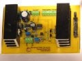
Therefore I'm on the right track in the illustration above. And yes, I do have a 0.1uF also on the other ICs in the other 4 circuits as well as larger caps. However they're not all 220uF.

Score circuit - has 1 x 100uF paralleled with a 0.1uF at Vcc entry
Count down timer - 1 x 100uF paralleled with a 0.1uF at Vcc entry
Clock - 3 x 100uF paralleled with 0.1uF - scattered throughout circuit
Temperature - 1 x 100uF + 0.1uF at Vcc entry.

If the above seems to work, do I need to change it (i.e. change to 220's and add more per circuit)?
 

Wendy

Joined Mar 24, 2008
23,797
From what I'm hearing, you are there. The difference between 220µF and 100µF is pretty small. Remember, these component are put in place just in case.
 

Thread Starter

chrischrischris

Joined Feb 18, 2012
317
Yea, I'm almost there.
I'm just preparing some powerpoints for our end of year soccer presentation for tonight, then I'll test out my power board and get back to you. Hopefully in a few hours.
Make that few hours to tomorrow - took longer than I thought.
 
Last edited:

Thread Starter

chrischrischris

Joined Feb 18, 2012
317
PWM and Vcc regulator PCB work well. I do find however I'm only delivering 22.6V via the power mosfet. Not really sure why. But the displays still seem pretty bright in direct sunlight, so maybe running a little less bright is better for the LEDs.

Next... the frame. Time to get the angle grinder and welder out!


By the way, for the writing on the board I printed it on photo gloss copy paper and ironed it on. Then I used a circuit board lacquer spray to seal it. I also sprayed the base of the board lightly after finishing all the soldering (to seal it and stop tarnishing).
 

Attachments

Thread Starter

chrischrischris

Joined Feb 18, 2012
317
Hi Bill / elec_mech.

As I mentioned I have my scoreboard finished and put up in place. The club loves it. However even though everything worked with on the ground, I then found some elec problems after installing. Last week someone in the club put their hand up to help out (seems to be in the LED business and know electronics), but now I can't really afford to not have the board delay in working, so can I ask you both a question or 2.

Bill: The power/PWM circuit that you helped me with seems to be overheating. I placed an IN5401 diode where the 24V was feed to the board as a safety. Now I find at low intensity of the digits it's all fine. When it's sunny weather and PWM turn up full, the diode gets too hot to touch as well as the trace leading to the transistor/mosfet combination. In the attachments below, the PCB diagram shows the trace that's overheating. On my first board something blew as a result. In my "spare board" it's overheating too, so I'm not running it yet. Possibility - something elsewhere is shorting? or is it on the board?
Power fault PCB.jpg Power fault circuit.jpg Power fault board part list.jpg

elec_mech: I'm guessing this is a fault on my printed circuit board... On the first one I made, I could set to say 45:00, then start the count down - 44:59, 44:58, 44:57...00:00. On my second (newer, better board) I did make slight trace alterations to compact the board a bit. In doing so, I think I mis-wired. Now when I count down from either the preset of 45:00, it starts the display at 46:59, then 46:58, etc. When's it's done 1 minute, it then jumps down to 43:59. This means it keeps the correct time, but instead of displaying 44 minutes then 43, then 42 down to 00, it displays 46, then 43, then 42 down to 00. I haven't tested it on every minute down, but to start with I'm trying to solve why a "6" rather than "3". My circuit diagram hasn't changed, just my PCB and I'm having difficulty finding it. I'll keep looking but I was just wondering if off hand you might have seen this problem before and can direct me. I will be going into this myself further tomorrow, so don't know yourself out over it - it's my mistake.

Timer fault circuit.jpg Timer fault PCB.jpg
 

Wendy

Joined Mar 24, 2008
23,797
The diode is probably under rated, or needs more lead length to cool it. Measure the max current through the diode (remove it and replace with amp meter), then find a diode with double the rating you measured. Make the leads as long as practical, this will serve as a informal heat sink. You might also look for a Schottky diode, they drop less voltage and so dissipate less wattage (the current experiment still applies). You can get diodes that are designed for heat sinks, though I doubt you will need to go for such a radical solution.
 

Thread Starter

chrischrischris

Joined Feb 18, 2012
317
Thanks Bill. So you don't think there's something wrong in the circuit - only the diode is under rated??

The spec sheet says the IN5401 has a max forward current of 3A, rms voltage of 70 and max repetative peak voltage of 100. Does this mean that at 100V it's 3A, so at 24V it is about 12A? Or do I look at rms volts (70V, 3A, which ends up 70x3/24 = about 9A)?

From my previous calculations, the digits were drawing around 11 to 12A at 24V DC. The next size up diode (IN5402) seems to handle 140V and 200 respectively (and 3A). So maybe this would be better?
 

Relayer

Joined Jan 1, 2013
18
Hello Chris,
I'm just wondering about R4 and R8. They actually look like inductors that Jaycar sells. The light green color gives them away.
Could you please measure them to make sure each is actually 1k2 as per your circuit diagram.
As for a robust diode, you can purchase the FR607 diode from Jaycar. That should be able to handle the current and PWM requirements of the circuit, as its a Fast Recovery and rated at 6 Amps. Though I suspect you have a fault some where, as the trace and diode should not be overheating.
Regards,
Relayer :D:D:D
 

Thread Starter

chrischrischris

Joined Feb 18, 2012
317
Hey Relayer, we spotted with the Jaycar purchase! Yes I think I got them in a packet of 10 because I have 4 left in my parts box, which means I used 2 on one board and 2 on the spare board. I just measured them and they are 1k2Ω. Not sure why these were green however.

Just looked up the FR607 from Jaycar - $15'sh per pkt 10. Seems to have the same spec as my IN5401 except 6A instead of 3. Could I instead use an IN5408 which handles 1000V at 3A? They can be bought single at 30c each?

Yes, the trace being heated I think was transfer of heat from the diode possibly. Have you looked at the wiring diagram? If so, could you see a problem with this circuit stand alone?
 

Relayer

Joined Jan 1, 2013
18
Could I instead use an IN5408 which handles 1000V at 3A? They can be bought single at 30c each?
Hey Chris,
It seems the diode has been installed as an afterthought. The only purpose I can think of as to why its been installed is for reverse polarity protection. (Though someone else can enlighten me as to its function).

Since the diode is in line with the 24V rail, therefore the diode should be able to conduct at least 12 Amps, as per the Supply Voltage/PWM Circuits.
Both the 1N5401 and the 1N5408 fall way short of the current required. I'm not surprised the diode is overheating. Though your trace wire may need some shoring up. i.e. Use solder to thicken the track going from the diodes cathode to the source of the MOSFET. Won't hurt to do the Drain track and your grounds going to your LED arrays. Basically any track that needs to carry the 11.7 Amps required by the LED arrays.

If its absolutely necessary to have the high current diode in circuit, then I would suggest you use the Jaycar double Schottky diode MBR20100CT, as this can easily carry 20 Amps without breaking a sweat.

As for falling short of the 24 volts required, you should be able to adjust VR2 to get the 24 Volts close to spot on, though do the adjustment under load.
I hope the above helps. ;)
Regards,
Relayer :D:D:D
 

Thread Starter

chrischrischris

Joined Feb 18, 2012
317
Thanks Relayer. Yes the IN5401 was an after thought. In a clock circuit I found on the web (Doctronics), I read that there should be an in-line diode I think from memory in case of reverse polarity connection. I chose the diode as it was the same one running this clock (which in hind sight draws almost no current in the clock circuit). I know this sounds quite ignorant, but given the IN5401 looked so large, I simply assumed it could carry the load. The schottky is the better way to go (also as suggested by Bill Marsden in an earlier reply). Cost of diode is only around $2.

However, should I simply be installing a fuse on the 24V line that is connected to the circuit? I don't really see reverse polarity as an issue here, but rather spike overload if the switching powersupply surges for some reason.

Yes, I'll also build up the trace wires - they do look a little "thin" given 12A at 24V. I was thinking the same thing when I made the board. As for adjusting VR2, yes, I will be adjusting this once it is all operating. Thanks again.
 

Relayer

Joined Jan 1, 2013
18
Thanks Relayer.
You're welcome ;)

I don't really see reverse polarity as an issue here, but rather spike overload if the switching powersupply surges for some reason.
I agree, reverse polarity protection would be a bit moot, though spike suppression wouldn't be out of the question. Though your main supply should have the suppression, not your secondary supply, with say a Metal Oxide Varistor connected across your mains input after your mains fuse.
The one in the Jaycar Catalog number: RN-3404 would be an ideal choice.
Though I do recommend you place an appropriate size piece of heatshrink over the Varistor, You will eventually need to replace the Varistor after say 3 to 5 years, as these devices can deteriorate over time due to internal molecular changes.
Some years ago I was heavily into repair and modifications to the first line of X-Box's (pre X-Box 360), and in quite a few repairs I've had to replace the Varistor in the PSU's, as they had failed prematurely. Some in fact flamed up when they failed, as I found evidence around the components installed near the Varistor. Hence the need of heatshrink. It should contain any flames if the device fails.

However, should I simply be installing a fuse on the 24V line that is connected to the circuit?
No. I doubt you'll readily find a 12 Amp fast blow fuse.
As I've said, the spike suppression should start at your PSU's front end.

Once again, I hope the above helps. :)
Regards,
Relayer :D:D:D

P.S. Do you have the schematic for the PSU itself? i.e. rectifier diodes, transformer (if used) etc...
 

Relayer

Joined Jan 1, 2013
18

elec_mech

Joined Nov 12, 2008
1,500
I'm guessing this is a fault on my printed circuit board... On the first one I made, I could set to say 45:00, then start the count down - 44:59, 44:58, 44:57...00:00. On my second (newer, better board) I did make slight trace alterations to compact the board a bit. In doing so, I think I mis-wired. Now when I count down from either the preset of 45:00, it starts the display at 46:59, then 46:58, etc. When's it's done 1 minute, it then jumps down to 43:59. This means it keeps the correct time, but instead of displaying 44 minutes then 43, then 42 down to 00, it displays 46, then 43, then 42 down to 00. I haven't tested it on every minute down, but to start with I'm trying to solve why a "6" rather than "3". My circuit diagram hasn't changed, just my PCB and I'm having difficulty finding it. I'll keep looking but I was just wondering if off hand you might have seen this problem before and can direct me. I will be going into this myself further tomorrow, so don't know yourself out over it - it's my mistake.
Hmm, it sounds like the 4511 is seeing a high signal on pin 1 (B) when it should be zero (first guess anyway).

My suggestion would be to let it count down to at least 30:00 and see if you notice any other discrepancies. If something is wired wrong, you should see a pattern which would help us narrow in on the issue.
 

Thread Starter

chrischrischris

Joined Feb 18, 2012
317
My suggestion would be to let it count down to at least 30:00 and see if you notice any other discrepancies. If something is wired wrong, you should see a pattern which would help us narrow in on the issue.
Yes, I agree. On the weekend I spent a few hours checking the circuit layout against the PCB layout. I did have all the diodes mis-labelled between them, but that is all I could see wrong. There is one inconsistency however between the 2. On the schematic, there is a 10k pull down resistor just prior to pin 12 of the 4060 (with a label on the line saying "stop count when "00:00: reached. If you follow that line up where it meets 2 diodes, there is a label showing it goes to Vcc. However in the PCB is is connected to Vcc via a 10K pull up resistor. So in the actual build this one line is both being pulled up and pulled down at the same time with the same value resistor. Does that make any sense?
 

Thread Starter

chrischrischris

Joined Feb 18, 2012
317
Yep. It is common to kludge PCB to fix them. Did you do this?
I drew the circuit first and labelled it with things such as Resistor or 470Ω. When I then drew the PCB, I started to part number these. I later updated the circuit diagram to match the PCB, but with the diodes as they were so confusing, I had the numbers wrong. I just updated my file last night. Eventually I'll double check them all.:D
 
Top