Connecting USB with MCU

Thread Starter

shibin_varghese

Joined Jan 14, 2019
73
Hi Friends,
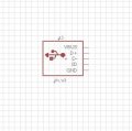
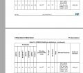
Here I am attaching the datasheet of an MCU of STMicroelectronics and a typical pin configuration of a USB 2.0.
PA11 and PA12 of the controller are assumed for USB_DM and USB-DP respectively.
Can I directly connect those pin to the USB through a series 15R resistor and a TVS Diode in parallel to protect those data lines?.
Some images from google suggest that we need a pull up of 1.5K to the D+ line and I am not very sure about it.
Would someone be able to explain this to me?.
 

Attachments

Irving

Joined Jan 30, 2016
3,843
The series resistors need to be considered in conjunction with the PCB layout, which will also impact the impedance, depending on 2 or 4-layer PCB, board material, trace width/thickness/length, etc. etc.

See here for a Stack Exchange thread on the subject. There are others there and here on AAC too. I found this guidelines doc from Ti useful too.
 

Thread Starter

shibin_varghese

Joined Jan 14, 2019
73
The series resistors need to be considered in conjunction with the PCB layout, which will also impact the impedance, depending on 2 or 4-layer PCB, board material, trace width/thickness/length, etc. etc.

See here for a Stack Exchange thread on the subject. There are others there and here on AAC too. I found this guidelines doc from Ti useful too.
Thank you for your reply. I think the rest of the design is fine other than the series resistance. Can I move forward with the idea?.
 

Irving

Joined Jan 30, 2016
3,843
Only you can decide that! As a breadboarded solution for testing or a small scale, low speed prototype, probably. As a design for large scale manufacturing, maybe. You may need to prototype that PCB, or just a small section, to see what effect if any those ESD parts have in conjunction with your layout, track dimensions, etc. at full speed.
 

ericgibbs

Joined Jan 29, 2010
18,766
hi sb,
What is the distance between the MicroB and the receiving module, also what form is the link cable.?
I assume the +/-D receiver unit is at the same ground as the MicroB.

E
 

Irving

Joined Jan 30, 2016
3,843
hi sb,
What is the distance between the MicroB and the receiving module, also what form is the link cable.?
I assume the +/-D receiver unit is at the same ground as the MicroB.

E
Hi Eric,
The MicroB connector is the USB socket so is on the same ground as the STM micro. I don't think there's any cable, just PCB traces.
 

Irving

Joined Jan 30, 2016
3,843
hi I,
I read the TS text a number of times, but I was not sure how it was configured, as they say.. 'if in doubt ask'

E
Fair enough.

Though I am intrigued by the resistor value of 15E in the last diagram. Can't recall ever seeing that in an eCAD package, normally blank or R for non-multiplier values.
 

Thread Starter

shibin_varghese

Joined Jan 14, 2019
73
The D+ and D- nets are routed as differential pairs. So they have equal length. I think my design is enough for a preliminary designing of USB and corrections can be made in the succeeding versions.
 
Top