 Facebook
 Google
 GitHub
 Linkedin
Hi,
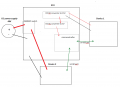
I'm designing an ECU for our prototype. This will manage the power supplies to 2 different devices and also some data processing through a microcontroller. The image below is a basic block diagram of the system (sorry it does not look very nice).
I am using a 48V power supply, which is stepped down to 15V to power Device 1, and further stepped down to 5V to power the microcontroller. I am using non isolated DCDC converters from TracoPower. Device 2 uses 48V so it is connected to the battery through a mosfet switch.
Device 1 manages connection to the cloud.
Device 2 controls a motor.
mega2560 is used for the microcontroller.
My concern is how to properly connect the grounds. I've read about ground loops, I dont fully understand it but I want to avoid it as much as possible.
Here are some of my questions and concerns.
- should I separate the GND of the microcontroller part (5V) with the GND of the rest of the ECU board? The GND of the 5V dcdc converter will then be the connecting point between the 2 GNDs. I've read about star grounding before, but i'm not sure if this is the right application.
- Both devices are connected through a power cable (+) and (-). I thought the (-) wire is the only point where the GNDs of the 3 boards connect, but the serial connection between the devices and the microcontroller has a GND pin, will this cause a ground loop? or any other problem in the future?
- I'm using a 4 layer PCB for the ECU. What is the proper way of making ground planes? Should I make a GND plane in all the layers and connect them using vias? and if I separate the GND of the microcontroller part, is it ok to make a small GND plane portion for it? or just tracks are fine?
Attachments
-
 66.3 KB Views: 0


