circuit simulation program difference results

Thread Starter

aragon1971

Joined Apr 7, 2008
160
hi
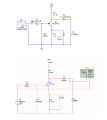
i study a FET common source amplifier and i make a simulation first in circuit make pro 200 and multisim
i use a ac signal with peak amplitude 20mV and frequency 1 KHz the outiput signal have difference amplitude in two simulation
program
in multisim the amplitude of output signal is 244,mV
and is circut maker pro 2000 is 770.75 mV
what is this difference due to?

thank George
 

Attachments

crutschow

Joined Mar 14, 2008
38,316
Are your sure the two input signals are identical?

Otherwise it may be a difference in the two transistor models.
You circuit depends upon the transconductance (gm) or admittance (Yfs) gain of the transistor, and the two models may have a different value for that.

Normally, you want to design a circuit with negative feedback, so the gain is not highly dependent on the transistor gain, since that has significant unit-to-unit variations in real devices (look at the data sheet which shows over a 2:1 variation).
 
Last edited:

Ramussons

Joined May 3, 2013
1,567
yes meaybe the diference type of fet in multisin the BF245C DONT WORK !
In practice, feedback is used to ensure that parameters like Gain is independent of the Active Device ( transistor, FET, ....) Parameter variations.
If you remove that 25uF capacitor, you will implement an AC feedback, and your gain should be almost the same, about 4.
 

Thread Starter

aragon1971

Joined Apr 7, 2008
160
In practice, feedback is used to ensure that parameters like Gain is independent of the Active Device ( transistor, FET, ....) Parameter variations.
If you remove that 25uF capacitor, you will implement an AC feedback, and your gain should be almost the same, about 4.
yes! when remove the capacitor then the gain from the two different sofware are equal
 
Top