Circuit needed for vintage game

Thread Starter

geofflove

Joined Apr 12, 2023
3
I have a vintage trade stimulator bartop game from 1965. It's not working...! Strangely the circuit board has CMOS chips on it which I don't think were around in 1965 so guess it's been replaced at some point - there is no information online and I have no schematic.

I'm thinking of replacing the whole board with a new one and need to design a circuit..... It needs to do the following:

Use almost no power when dormant and activate when I microswitch is momentarily activated (by inserting a coin).
Wait for 5 different microswitches to be momentarily triggers (by balls falling into the holes in any order)
Once all five have been triggered, light a lamp and play a sound for a short time then go back into 'sleep' mode.
If all five switches aren't triggered it still needs to sleep after a short while or resent when a new coin is inserted.

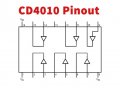
The existing circuit used 2 chips - a 4009 and 4010 plus a few transistors.

Can anyone suggest a most efficient way to do this with a circuit? I'd love to bring this back to life!

Thanks!

IMG_0372.JPG
IMG_8258.JPEG

IMG_8259.JPEG
 

AnalogKid

Joined Aug 1, 2013
11,055
Almost everyone will say that the most "efficient" way to implement the game functions is with a small microcontroller (uC). From a circuit design standpoint, not much fun. But if you already are up on a programming language, have a development environment and programmer, etc., then a uC will the the shortest path to a replacement circuit. Beyond generalities, we need more information.

Close-up images of the lettering on both chips - They probably were not CMOS. The left chip looks like CM4010AE. This might be CMOS, since the date code is December, 1973.

Close-up image of the pc board

Better image of the top (playing surface) of the game.

What kind of sound did the game produce?

ak
 

Thread Starter

geofflove

Joined Apr 12, 2023
3
Here's a few more pics. One chip is indeed CM4010AE. Thye name has worn a bit on the the other but I'm pretty sure it reads as a CM4009AE which I understand is the inverting version of the same chip? The transistors are Motorola 252's and 251's which I understand are germanium PNP's which I might struggle to find. First choice would obviously be to get this circuit working. I'm considering replacing the electrolitic caps which might have dried out by now and swapping the chips. for 4049 and 4050 which I understand are the same to see if that helps. At the moment when a batter is connected and the 'start' microswitch activated by the coin push is held in there is a click from the speaker and win light comes on. But that's it. Could be a transistor too I guess?

In the pics you'll see the microswitch at the top which is operated by the coin push. In the centre are the 5 microswitches which the falling ball triggers. There is also a pair of cut wires coming from the board. I see that there is a 'tilt' light - the device was menat to disable if tilted. However, I can find a tilt switch anywhere so am guessing that's where they used to go. As to what sounds it used to make I've no clue sadly - I've just purchased this so know nothing!

I don't have a programmer etc so am looking for a more old school method ideally!
Thanks for your help!

IMG_8282.JPEG
IMG_8285.JPEG
IMG_8286.JPEG
 

Ron314

Joined Mar 14, 2023
21
Interesting project! I agree with trying to restoring it vs. rebuilding it with something more modern. The tilt switch was most likely a mercury switch and possibly sat right where the green and yellow wires came to an end. Or maybe it was a weight of some sort and was related to that microswitch near there as well, which I can't seem to find what it was used for. Anyhow it appears that there was something screwed in there, that is now missing. This might be stopping your game from working since a tilt condition would stop the game from operating.
The brown cut wires.......?
 

AnalogKid

Joined Aug 1, 2013
11,055
Note that the 4010 pin 2 is not in its socket.

Those socket pins were very popular in the 70's because they were cheap. I still have some and strongly recommend *against* using them for anything. A common problem was the sides of the sockets touching each other, so check for that.

ak
 

Thread Starter

geofflove

Joined Apr 12, 2023
3
In addition to the yellow/green wires not connected there is also a heavy black pair which are cut off - ending centre picture. While the microswitch at the bottom of the pics looks like it doesn't do anything it is actually activated when the coin slide is pushed all the way in. This is what 'activates' the circuit while the balls are released by mechanical means. Usually most tilt mechs work by closing when tilted so I suspect not having one connected shouldn't stop operation.
There is some light corrosion on some IC pins and taking on board the comment above re the sockets maybe I should fit new sockets when changing the capacitors?

There's not much info online re the transistors (Motorola 251 and 252's but also with the number 40006 and 40005 on them). What I could find (if I'm looking at the correct numbers) suggested they were general purpose germanium pnp 200mw devices - not sure the difference between them. Anyone any clue what they might be replaced by?

Thanks for the help everyone!
 

Dodgydave

Joined Jun 22, 2012
11,304
I would start by drawing the chips and seeing where the pins go to , and try to work out how it works, the transistors can be replaced with modern pnp types . Otherwise it's a microcontroller. Cd 4010 is a hex buffer, CD 4009 is a hex inverter, some of the capacitors are probably
for time delays ..


3514179b92-cd4009.png
 

Attachments

Last edited:
Top