Facebook
 Google
 GitHub
 Linkedin
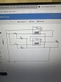
I need help with a basic circuit that I’ve been working on consisting of 2 NC switches that I’ve been using to power the coils on 2 24v sp relays individually.
Through the contacts I’ve wired in series an led that comes on when both switches are in there dead state.
I also want to have individual leds for each of the switches I tried to use the NC contact on the relays but end up with one of the leds permanently live as it’s fed from the 24 supply for the series circuit as described before
any ideas please
Last edited by a moderator: