 Facebook
 Google
 GitHub
 Linkedin
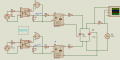
I designed this circuit to control a TCR (Thyristor Controlled Reactor) using two SCRs in antiparallel, which should be triggered through two MOC3021 drivers. To properly supply the MOCs and maintain isolation, I included a 4N25, whose function is to increase the voltage of the 3.3 V pulses and isolate the control side from the power stage. In theory, when I apply the pulses, the MOCs should activate the SCRs and thus modify the waveform of the current on the load. However, it is not working: at the output I only observe the sinusoidal signal unchanged, as if the thyristors never trigger. That is why I need help to identify what is failing in the triggering stage and what adjustments I should make so that the circuit works as intended.
Attachments
-
 30.9 KB Views: 28


")


