 Facebook
 Google
 GitHub
 Linkedin
Hi Guys,
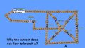
I just don't know why the current does not flow through branch A.
Please see attached file
Thank you a lot, i am still a beginner here.
I receive any feedback and suggestion.
I just don't know why the current does not flow through branch A.
Please see attached file
Thank you a lot, i am still a beginner here.
I receive any feedback and suggestion.
Attachments
-
 103.8 KB Views: 84


![BranchA[1].png](/data/attachments/63/63902-8fe797a398d4051055b19922a481ed11.jpg)


