
 Facebook
 Google
 GitHub
 Linkedin
Attached is the problem and my work.
I am using circuit analysis to find the power dissipated in a Zener Diode. I used the loop method to solve for $$I_1$$
It seems like my error is during this process. I view crossing the cathode (-) up toward the anode (+) as going uphill / going toward a positive potential. For that reason I should get a +20V, just as I would get a +25V for traveling up the DC source.
This leads to the wrong answer, apparently it should be -20V for the diode, based on the fact the answer is given in the question (2W) and my answer is 18W.
Any help understanding why the same conventional signs dont apply for Diodes as they would EMFs ?
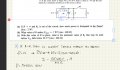
I am using circuit analysis to find the power dissipated in a Zener Diode. I used the loop method to solve for $$I_1$$
It seems like my error is during this process. I view crossing the cathode (-) up toward the anode (+) as going uphill / going toward a positive potential. For that reason I should get a +20V, just as I would get a +25V for traveling up the DC source.
This leads to the wrong answer, apparently it should be -20V for the diode, based on the fact the answer is given in the question (2W) and my answer is 18W.
Any help understanding why the same conventional signs dont apply for Diodes as they would EMFs ?






