Facebook
 Google
 GitHub
 Linkedin
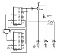
Here's a version for 16 leds:I am used to building novelty led chaser kits and diy circuits that chase. It’s usually a single led lighting up and moving through a line or circle as one on then off next on then of etc around or down a line of LEDs. I want a circuit to control 16 LEDs in a chaser effect that has the reverse going on. All LEDs are on and the moving effect is one led in turn goes off while it moves down the line or in my case around the circle.
Any help or direction would be helpful. Thank You

It is designed for 6v-15 but should be ok to operate at 5v.
I didn't know if you wanted a reset but that can also be added.
Last edited: