 Facebook
 Google
 GitHub
 Linkedin
I have a (maybe stupid) question.
I am designing and building various little circuits for RC aircraft. I have built some electronic switches for different purposes. For example to control the ignition of a gasoline engine or to switch ON/OFF the entire power supply of an aircraft.
In the former it is very straightforward. I am using an Attiny85, an opto coupler and an N Channel enhacement type logic level MOSFET for low side switching.
For a main switch this approach is not preferred as the usual way of controlling the power is high side switching. High side switching with a P channel MOSFET has known problems. First of all, P channel MOSFETs have a higher RDS ON values. But a more serious problem is that in high side switching the switching performance depends on the input voltage. For example, if I use an input voltage of 5 V (which is a standart value for RC systems) the P channel MOSFET would not conduct fully even if I tie the gate to ground because -5V VGS is not sufficient to fully open the MOSFET.
Of course there are numerous solutions for MOSFET gate drive but I want to experiment a little bit using discrete components which I already have.
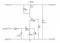
My plan is to pull the gate of the P channel MOSFET to a lower level than the GND and achieve saturation of the MOSFET as much as possible. I think I can construct a simple charge pump for a negative voltage and feed it with an output from the Attiny85 with a PWM signal (duty cycle 50%). This negative voltage will be connected to the emitter of an NPN transistor (like 2N2222) which has it's base connected to ground and it's collector connected to the gate of the P channel MOSFET.
The proposed schematic is attached.
I really don't have the time to test this circuit on a breadboard until mid April. So I would like to hear your comments about this circuit. Thank you very much.
I am designing and building various little circuits for RC aircraft. I have built some electronic switches for different purposes. For example to control the ignition of a gasoline engine or to switch ON/OFF the entire power supply of an aircraft.
In the former it is very straightforward. I am using an Attiny85, an opto coupler and an N Channel enhacement type logic level MOSFET for low side switching.
For a main switch this approach is not preferred as the usual way of controlling the power is high side switching. High side switching with a P channel MOSFET has known problems. First of all, P channel MOSFETs have a higher RDS ON values. But a more serious problem is that in high side switching the switching performance depends on the input voltage. For example, if I use an input voltage of 5 V (which is a standart value for RC systems) the P channel MOSFET would not conduct fully even if I tie the gate to ground because -5V VGS is not sufficient to fully open the MOSFET.
Of course there are numerous solutions for MOSFET gate drive but I want to experiment a little bit using discrete components which I already have.
My plan is to pull the gate of the P channel MOSFET to a lower level than the GND and achieve saturation of the MOSFET as much as possible. I think I can construct a simple charge pump for a negative voltage and feed it with an output from the Attiny85 with a PWM signal (duty cycle 50%). This negative voltage will be connected to the emitter of an NPN transistor (like 2N2222) which has it's base connected to ground and it's collector connected to the gate of the P channel MOSFET.
The proposed schematic is attached.
I really don't have the time to test this circuit on a breadboard until mid April. So I would like to hear your comments about this circuit. Thank you very much.
Attachments
-
 71.6 KB Views: 85
")


