Cd4060 not pumping my 555 on monostable please help :)

Thread Starter

diddley230

Joined Mar 8, 2025
1
Hey guys.
Iv got a little project (my first project)
Making a timer thats off for 4 hours and on for 1 minute. (To stop photoperiod plants from going to seed)
Im useing a cd4060 and a ne555p and a mosfet to achieve this to power my stream of 12w leds

My problem is iv got the 555 in monostable as it needs to keep the light pumping for 1 minute
And i need to intrigrate my cd4060 for my 4 hours off timing.
I have to flip flop the 555 to ground for it to start turn off. Then i need my cd4060 to trigger it with a pulse.
Im just confused as to where im going wrong. Its been a few days of me tinkering eith it but im stuck and would love some more knowledgeable advice.
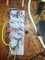
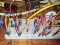
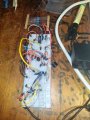
Iv attached some pictures of my breadboard in the hopes one ofnyou geniuses can help me solve it.
Its in a diagnostic 5 minute time with the oscelator right now but i still cant work it out.
 

Attachments

Ian0

Joined Aug 7, 2020
13,097
If you don't mind the timer being on for a minute and off for four hours and fifteen minutes there's an easier way.
(Or off for four hours and on for 56 seconds)
. . . but Eric's right - we can't tell you much until we see a circuit diagram.
 

AnalogKid

Joined Aug 1, 2013
12,049
I was going to suggest the 4.2667 hour approach but Ian beat me to it.

OR -

Get a 24-hour lamp timer at Walmart, set it for 1 minute every 4 hours, and plug your LED power supply into it.

ak
 

AnalogKid

Joined Aug 1, 2013
12,049
I see the 555 monostable circuit connected like this:
As implied above, the 4060 plus one resistor and one diode can produce a decoded 1-minute (-ish) pulse to drive the MOSFET. No 555 expressed or implied.

I would add a low-brightness LED to one of the lower bits as a 1 Hz heartbeat indicator to show the 4060 is running.

ak
 

sghioto

Joined Dec 31, 2017
8,633
Or off for four hours and on for 56 seconds)
Is this the correct configuration you are speaking of?
Initially there is a 56 sec delay and then the LEDs are ON for the first time followed by an appx 4 hour OFF time.
1741537990296.png
EDIT: Doesn't work correctly!
 
Last edited:

AnalogKid

Joined Aug 1, 2013
12,049
Initially there is a 56 sec delay and then the LEDs are ON for the first time followed by an appx 4 hour OFF time.
Don't think so. If the "N channel MOSFET" is the relay driver, then Q6 will pulse 255 (127?) times before Q14 changes state. You need to AND Q6 and Q14 to catch the first Q6 high state *after* the Q14 goes high (at the end of the 8192 count delay).

Here is a first pass at a basic schematic. R1-C1 set the oscillator period per the 4060 datasheet. The schematic shows a 1% resistor only because that is what is in my design library. Since the cap tolerance will be something like +/-10%, the resistor value is not super critical.

What is important is that the Q14 output be low for 4 hours (-ish) then go high. This equates to an 8 hour cycle period of 16,384 counts. While Q14 is low for 8,192 oscillator cycles, D2 holds the 4060 Reset input low even though Q6 is changing state every minute. After 8,192 counts, Q14 goes high, energizes the relay, and releases the D2 diode clamp on the Reset input. At this point, Q4 through Q13 are low, so Q6 does not immediately Reset the 4060. 32 counts later - approx. 1 minute - Q6 goes high, which resets the 4060, which turns off the relay, and the cycle repeats.

NOTE that this circuit has an inherent timing error. 1 minute every 4 hours is a ratio of 239:1, while one count every 257 counts (counting Q6) is a ratio of 256:1. The error is a little under 7%. You can select R1 ans C1 for a nearly perfect 1 minute ON time, with a longer OFF time; or a 4-hour OFF time with a shorter ON time; or some compromise value. For adjustability, replace R1 with a 130K resistor in series with a 50K trimpot.

ak

!!4-Hr-1-Min-Cycle-1-c.gif
 
Last edited:
Top