 Facebook
 Google
 GitHub
 Linkedin
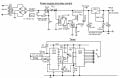
I've built two timers one using CD4060 and 4017 chips, it has 9 ranges and is 'spot on' down to the last second, so I built another using plain old 4060 and 4017.... as I increase the range it seems to add two seconds to every step...! This is to replace a uV mechanical timer in a uV lightbox.... no room for a digital otherwise I would have used one of them.
Both uses the same components, the high value resistors are 1% types and a 5% 1uF timing cap. I can only think it's the plain old chips I used - would I be right? The trip input goes to the rotary switch arm, so when this goes 'high' the thing will trip off . https://www.learningelectronics.net/circuits/egg-timer.html
Take no notice of the 400mA fuse.... far too high, this was a ICP fuse. Thanks, Dave.
Attachments
-
 441.7 KB Views: 66


