HELP WITH 4017 RESET

Thread Starter

dave321

Joined Dec 10, 2010
65
hi,
i need your help again guys......
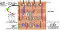
i have made the attached circuit, which i wanted to reset after the 5th output, so i connectected the reset pin15 to pin 1, but it behaves erratically and outputs up to 8? not 5.
C1 is between pins 15 and 16
(the trigger is a ~200ms pulse from a 555 monostable feeding pin 14)
what have i done wrong ?
 

Attachments

Thread Starter

dave321

Joined Dec 10, 2010
65
i only have the veroboard schematic
c1 and r7 ensures it turns on pin3 (the green led) on Turn On (this is a power -on reset circuit)
 
Last edited:

bertus

Joined Apr 5, 2008
22,882
Hello,

Please give the parts unique numbers.
Now i see 3 times R1, R2, R3 and R4.
I also see 2 times C1 and C2.
Post a complete schematic.
A veroboard placing pattern is not a schematic.

Bertus
 

dl324

Joined Mar 30, 2015
18,218
C1 is between pins 15 and 16
1767974253519.png
That cap wouldn't explain why the counter sometimes counts to 8, but not 9. I'd check your wiring.

The 33 ohm resistors between the outputs and gates aren't necessary. The pull-down resistors on the gates could be larger (10k). Since the counter is always enabled, R6 can be replaced with a wire. I'd make the pull-down resistor on the reset pin 10K.

Trying to source about 14mA for the LED isn't going to work. Typical is closer to 2.5mA with a little over 1mA guaranteed.
i only have the veroboard schematic
That's a wiring diagram, not a schematic.
 

Thread Starter

dave321

Joined Dec 10, 2010
65
View attachment 361786
That cap wouldn't explain why the counter sometimes counts to 8, but not 9. I'd check your wiring.

The 33 ohm resistors between the outputs and gates aren't necessary. The pull-down resistors on the gates could be larger (10k). Since the counter is always enabled, R6 can be replaced with a wire. I'd make the pull-down resistor on the reset pin 10K.

Trying to source about 14mA for the LED isn't going to work. Typical is closer to 2.5mA with a little over 1mA guaranteed.
That's a wiring diagram, not a schematic.
wow! thank you for drawing the schematic out for me i really appreciate that !!!!
i will try out your suggestion re R6 (CHANGE TO WIRE) and R7 change to 10k
 

sghioto

Joined Dec 31, 2017
8,633
hi , SGHIOTO, thanks for your previous help on other project, appreciated !
surely putting the diode between pin 15 and pin 1 will prevent the reset ,as drawn ??
No. When pin1 goes High pin15 goes High through the diode D2.
C1 and R7 still provide reset on power up.
Also suggest adding R10 and C4 to the 555 circuit.
When SW1 is pressed a single pulse will be sent regardless how long the switch is held low.
1767977319421.png
 

Thread Starter

dave321

Joined Dec 10, 2010
65
wow! thank you for drawing the schematic out for me i really appreciate that !!!!
i will try out your suggestion re R6 (CHANGE TO WIRE) and R7 change to 10k
changing R6 (CHANGE TO WIRE) and R7 change to 10k , did not solve the problem of erratic counting, strange.
maybe the one shot is not acting as a debounce circuit ? maybe sghioto has a point adding a cap and resistor to the 555 circuit.
i will try this tomorow
 

MrChips

Joined Oct 2, 2009
34,628
Maybe I am wrong. Maybe the 555-timer output pulse is too short.
I will check that.
I retract everything I said before. I breadboarded your circuit and could not find anything wrong.
I would try the following.

Instead of C3 = 220 μF across the 555 power rails, change this to 10 μF and 0.1 μF in parallel.
Also, add another 0.1 μF across pins 8 and 16 of the 4017.

Also try changing LM555 to a CMOS version, LMC555 or TLC555. In future, choose CMOS 555-timer chips. LM555 is known for producing glitches on the power rails.
 

Thread Starter

dave321

Joined Dec 10, 2010
65
The pulse width is fine but C1 should be 10nf, R7 10K, D2 not needed.
R10 and C4 required on the 555 circuit.
Verified on a bench test.
ok i will change c1 to 10nf, R7 i have changed to 10k already, and i will ADD R10 and c4 on the 555 circuit and get back to you. I appreciate your time with this !
 

Thread Starter

dave321

Joined Dec 10, 2010
65
ok i will change c1 to 10nf, R7 i have changed to 10k already, and i will ADD R10 and c4 on the 555 circuit and get back to you. I appreciate your time with this !
i changed c1 to 10nf on the 4017, and added r10 and c4 on the 555.
adding r10 and c4 seemed to stop the 555 from outputting a pulse.???maybe bad connction?
removing the 10nf cap it was pulsing as before.
still giving erractic counting output
 
Top