Decoder encoder using 4017 with IR LED For transmitter

Thread Starter

KRAB

Joined Aug 12, 2025
47
Dear all,
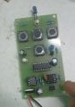
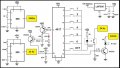
happy festival time. In fact,a few months back, i brought this issue. and got quiet a good amount of conceptual details clarified. Now, i have the circuit, and the PCB, too. for the IR Transmitter. Added it below. built ther circuit. tested with my handheld Velleman scope too. For some reasons, pin14 of IC 4017 IS NOT triggered and it shows aroudn 2.22 volts only from the opto. In addition, i could see a flicker at 24hz as a burst from IR LED. can you help me what is not going well . how to resolve it through. i thank the team of experts here for their excellent support in the past.
 

Attachments

sarahMCML

Joined May 11, 2019
695
Try putting a 1k resistor from pin 3 of the 24 Hz 555 to +5V. This will give you the full 5V pull-up on that pin, and you should now get more than 2.22 volts from the opto, which should now trigger the CD4017.
 

Thread Starter

KRAB

Joined Aug 12, 2025
47
Try putting a 1k resistor from pin 3 of the 24 Hz 555 to +5V. This will give you the full 5V pull-up on that pin, and you should now get more than 2.22 volts from the opto, which should now trigger the CD4017.
  • 24 Hz 555 output is already full swing
  • opto LED is already driven correctly. I checked.
  • The CD4017 is already clocking on edges
  • The 2.22 V of DMM is the only issue.

    So, not sure if this would help me. Thank you so much for your inputs pl.
 

sarahMCML

Joined May 11, 2019
695
You previously said the CD4017 was NOT being triggered! The DVM will only show 2.22V because the output pulse of the opto is not a constant value but a series of pulses, so the DVM will show an averaged voltage of those pulses!
 

Thread Starter

KRAB

Joined Aug 12, 2025
47
You previously said the CD4017 was NOT being triggered! The DVM will only show 2.22V because the output pulse of the opto is not a constant value but a series of pulses, so the DVM will show an averaged voltage of those pulses!
YES, You correct. for some reason, the pin14 is not getting the reqd. voltage to turn it high i believe. hence, the opto works, but the pin14 not getting min. voltage ( atleast 3.5v for high state). so, not sure what to do next.
 

sarahMCML

Joined May 11, 2019
695
Are you sure that pin 3 of the 555 is going to near 5V? Have you checked using a scope? The bipolar 555's outputs can usually only get to about 1.5V or so below V+, due to its darlington output stage, which will limit the voltage at the collector of the opto, and therefore at its emitter. Hence why I suggested adding a 1k pull-up to the 555's output.
 

Thread Starter

KRAB

Joined Aug 12, 2025
47
Are you sure that pin 3 of the 555 is going to near 5V? Have you checked using a scope? The bipolar 555's outputs can usually only get to about 1.5V or so below V+, due to its darlington output stage, which will limit the voltage at the collector of the opto, and therefore at its emitter. Hence why I suggested adding a 1k pull-up to the 555's output.
honestly, the scope i have could not help me to know the voltage but dmm shows around 2.22 volts. sure i will keep what you said as my option to check , thank you
 

Pyrex

Joined Feb 16, 2022
501
Replace IR LED driver 2N2222 to other transistor with higher hFE, say BC547B, base resistor 4.7 kOhm to 20 kOhm, resistor from pin 14 to Gnd - 20 kOhm to 100 kOhm
 

Thread Starter

KRAB

Joined Aug 12, 2025
47
Replace IR LED driver 2N2222 to other transistor with higher hFE, say BC547B, base resistor 4.7 kOhm to 20 kOhm, resistor from pin 14 to Gnd - 20 kOhm to 100 kOhm
the existing LED is working well. and also the 2n2222. may be i used the TO18 PACK, will the tag side connected to emitter. seems it is my mistake , i will reorient also. Thnaks.
 

Pyrex

Joined Feb 16, 2022
501
the existing LED is working well. and also the 2n2222. may be i used the TO18 PACK, will the tag side connected to emitter. seems it is my mistake , i will reorient also. Thnaks.
Those changes I suggested would help raise the voltage on pin 14 of the CD4017
 
Top