Decoder Encoder With 4017 Circuit Without Microcontroller.

Thread Starter

KRAB

Joined Aug 12, 2025
47
Hi All,

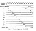
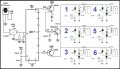
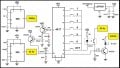
I am happy i am in safe hands. Thanks.Being a hobbyist and mechanicla background, i still explore to get soultuions for electronics as much i can. Now, i am building an IR Remote selector, but encoded / decoded without a microcontroller for choosing 3 outputs at Random. wHILE i was exploring the you tube and various sites, i found out the below answer with Trx and Rrx using 4017 and 555 .But still i could not understand how the selector switches gives 1, or, 2, or 3 or upto 6 pulses from Trx board to Rx board tHAT Gets same pulses and chooses the right output of 4017. i could not decipher its working from the circuit diagram attached by the person. he is also untraceable. Can you pl. help me how to read the Trx circuit. i attached the circuits for your ref. and also the you tube
for your ref. thanks.
 

Attachments

MisterBill2

Joined Jan 23, 2018
27,159
I examined the circuits shown, and while I can see the theory of how they should work, I would not be willing to say that they will work. Certainly it is an interesting concept, though.
 

Thread Starter

KRAB

Joined Aug 12, 2025
47
ooh ok, may i know the theory that you believe underlying the concept. still what failure modes you see . Leave alone that. i am eager to know the background theory. kindly enlighten me please. thank you.
 

drjohsmith

Joined Dec 13, 2021
1,548
ooh ok, may i know the theory that you believe underlying the concept. still what failure modes you see . Leave alone that. i am eager to know the background theory. kindly enlighten me please. thank you.
for the receiver,

Start with the data sheet of the 4017
https://www.ti.com/lit/ds/symlink/cd4017b.pdf

So this is a "counter" with a decoder output,

Upon a reset , output '0' ( pin 3 ) goes high, all other 9 output s go low
on each rising edge on clock input ( pin 14 ) , then the counter increments,
so on first clock, output 1 ( pin 2 ) goes high, all other 9 outputs go low.
on second clock, out put 2, etc,

It has a few interesting bits , like how it resets it self again on the 6th clock,
and that it is susceptible to any IR radiation, and it can be swamped easily , so as to be jammed.

Id strongly suggest that you simulate this in something like LT spice, to have a good understanding
a its a great tool to experiment in, a great skill to have, and it gives you detailed ino on how the circuit works.

There are some well experienced LT spice people on here, unfortunately I seem to have missed LT spice as my company uses different one . One day I will get into LT spcie.

just ask a new post ,how to go about simulating this circuit.


A typical IR system, would have encoding, such that it is hardened against false triggering, e.g your TV remote does not work on all TV's, and / OR be AC coupled to allow high gain and rejection of a flood of IR !
 

Attachments

MisterBill2

Joined Jan 23, 2018
27,159
INDEED!! The scheme is to send a number of pulses of 38 Khz modulated light to a broad spectrum, non-selective, receiver that will count the number of pulses received and operate the corresponding relay.
Certainly the scheme concept is valid, but just as certainly it depends on perfect reception to operate correctly. It is also not very secure from random triggering .
 

drjohsmith

Joined Dec 13, 2021
1,548
INDEED!! The scheme is to send a number of pulses of 38 Khz modulated light to a broad spectrum, non-selective, receiver that will count the number of pulses received and operate the corresponding relay.
Certainly the scheme concept is valid, but just as certainly it depends on perfect reception to operate correctly. It is also not very secure from random triggering .
I didn't look at the tx , as the receiver was bad enough . ..
The tx modulates the ir !
Wonder what that would do at the Rx .
 

MisterBill2

Joined Jan 23, 2018
27,159
Since the selection is made by counting pulses, it is more likely an effort to avoid false triggering. I do not recommend this scheme except for fiber-optic connected systems.
 

schmitt trigger

Joined Jul 12, 2010
2,027
Apparently the OP is in a different time zone, judging by the time he made post #1. If you are somewhere in North America, I would wait until tomorrow or late at night for his response.
 

schmitt trigger

Joined Jul 12, 2010
2,027
BTW, the receiver’s 1 uF capacitor hanging from the schmitt trigger is a both unnecessary and a big mistake.
Unnecessary because the IR receiver should eliminate any noise. If he wants to eliminate the probability of a runt pulse, then the filter should be before the ST, and certainly not with a time constant pulled out from thin air.
As is, the poor logic gate will only brute-force discharge the capacitor.
 

Thread Starter

KRAB

Joined Aug 12, 2025
47
for the receiver,

Start with the data sheet of the 4017
https://www.ti.com/lit/ds/symlink/cd4017b.pdf

So this is a "counter" with a decoder output,

Upon a reset , output '0' ( pin 3 ) goes high, all other 9 output s go low
on each rising edge on clock input ( pin 14 ) , then the counter increments,
so on first clock, output 1 ( pin 2 ) goes high, all other 9 outputs go low.
on second clock, out put 2, etc,

It has a few interesting bits , like how it resets it self again on the 6th clock,
and that it is susceptible to any IR radiation, and it can be swamped easily , so as to be jammed.

Id strongly suggest that you simulate this in something like LT spice, to have a good understanding
a its a great tool to experiment in, a great skill to have, and it gives you detailed ino on how the circuit works.

There are some well experienced LT spice people on here, unfortunately I seem to have missed LT spice as my company uses different one . One day I will get into LT spcie.

just ask a new post ,how to go about simulating this circuit.


A typical IR system, would have encoding, such that it is hardened against false triggering, e.g your TV remote does not work on all TV's, and / OR be AC coupled to allow high gain and rejection of a flood of IR !

mY Thanks to you. But, i am not clear on how , the output gets only one pulse, and the next output pin no 7 gets two pulses. same with pin 10 getting 3 and more. i am planning to stop for my need with three pulses. but sill i could not reason how it gives 1, 2, 3 exactly. i do not know about LTSPICE, and if i can get a hand to support it will be greatful.
 

drjohsmith

Joined Dec 13, 2021
1,548
mY Thanks to you. But, i am not clear on how , the output gets only one pulse, and the next output pin no 7 gets two pulses. same with pin 10 getting 3 and more. i am planning to stop for my need with three pulses. but sill i could not reason how it gives 1, 2, 3 exactly. i do not know about LTSPICE, and if i can get a hand to support it will be greatful.
the outputs of the 4017 count up, one is high , the rest low, on the next clock, the next output is high, the rest low,
look at the data sheet for the 4017.
 

sghioto

Joined Dec 31, 2017
8,633
But, i am not clear on how , the output gets only one pulse, and the next output pin no 7 gets two pulses. same with pin 10 getting 3 and more.
I'll try and explain the transmit circuit.
Before a button is pressed all output pins are Low except for pin3, the LED is OFF and the counter is reset to zero.
Now say we press button #1 connected to pin 4. Because the output on pin 4 is Low it activates the PC817 which starts sending pulses to the input counter pin14 at 24 pulses a second while simultaneously pulsing the 2N2222 IR LED transmitter.
After the second pulse is received pin 4 of the 4017 counter goes High which deactivates the PC817 shuting off the transmitter so only two pulses are sent.
During this same time frame and after the first pulse is received pin 3 goes Low and activates the LED.
This starts the delay timer which after a couple of seconds resets the counter back to zero.
Once the LED goes out the circuit is ready for another button push.
 

Thread Starter

KRAB

Joined Aug 12, 2025
47
the outputs of the 4017 count up, one is high , the rest low, on the next clock, the next output is high, the rest low,
look at the data sheet for the 4017.
thanks for your reply. still i am not clear how when we press a second switch pin no. 7 , it gives two pulses and the same for the succeding pins increasing the no. of pulses. apologies if i am asking a dumb question. pl. excuse me.
 

sghioto

Joined Dec 31, 2017
8,633
I explained that in post #16 I thought.
Actually starting at button #1 (pin 4) will produce 2 pulses and increment one more pulse for buttons 2 through 6.
 
Last edited:

drjohsmith

Joined Dec 13, 2021
1,548
thanks for your reply. still i am not clear how when we press a second switch pin no. 7 , it gives two pulses and the same for the succeding pins increasing the no. of pulses. apologies if i am asking a dumb question. pl. excuse me.
OK, so I think we need to know what you understand so far,

Can you explain the 4017 chip operation,
a clue, look in the data sheet.
In your own words , how does it work,
 

Thread Starter

KRAB

Joined Aug 12, 2025
47
OK, so I think we need to know what you understand so far,

Can you explain the 4017 chip operation,
a clue, look in the data sheet.
In your own words , how does it work,
Yes, sir, at a very high level overview i know, meaning, this is called as Johnson's counter, that upon triggering the input pin no 14, the outputs cascade one by one from pin 3,2,4,7,10,1,5,6,9,11 and if needed a carryover pin has to be triggered. the rest of the pins are grounded after the VCC to pin 16. pin 8, 13 are grounded.

uPON Every input trigger, the output pins goes high and ascends to every next pin on the above pattern. The output signal is a latched signal until and the next input trigger.

Note:The output pins, also can be used either as sourcing or sinking the current. I understand this as, the output pins can also be used for grounding( sinking). This is something for my understanding a new one. The circuit i had shared uses the sinking phenomenon to trigger the PC817 and thus the base pin of 2n2222, which then pushes 38khz signal and the IR LED Flashes.

My understanding stops here, and i scratch my head, how, the 24hz makes the pc817 and the 4017 to output more than one signal to IR LED.

SORRY, If i had missed some critical point and wish to learn it from you. Thanks.
 
Top