Facebook
 Google
 GitHub
 Linkedin
What kind of flip flops are inside the 4060?
I've built the 1Hz signal from the circuit I found online.. here (Crystal Controlled 1Hz Time Base ( Clock ))
Just got the components and stuff delivered yesterday from Mouser Electronics.
I've learned a little about the SR flip-flop, and T Flip-Flop from videos on YouTube.
Almost anyone can order the parts on Mouser Electronics, and hook up wires and components and build this thing, but to understand what's going on is a completely different story altogether.
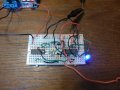
I'll post pictures and upload my video for the circuit with the blue 1Hz blinking LED along with my UT61D multimeter showing 0.999 Hz from the CD4027BE dual master-slave JK Flip-flop output.
I honestly don't know if it's 0.999 Hz or 1Hz, because of the accuracy of the DMM.
But I'm going to feed the 1Hz signal into a μC. I'm going to start simple and use the Arduino Uno, but I've also ordered the parts for a USBasp and some jumper wires.") , because I want to learn about ATmel AVR programming too.
, because I want to learn about ATmel AVR programming too.
So anyone want to walk me through and understanding the CD4060?
I'm a little lazy, but I found this video on YouTube talking about Binary Ripple Counter
I guess one of my biggest problems, is that the data sheet for the CD4060BE seems a little old, so I'm having a little trouble understand what pins are what and what they do.
My short video of the circuit 32.768KHz to 1Hz, Blue LED Blinking and DMM showing 0.999Hz on the output.

High Quality image of the circuit.

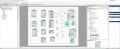
The Circuit on breadboard drawing.
I've built the 1Hz signal from the circuit I found online.. here (Crystal Controlled 1Hz Time Base ( Clock ))
Just got the components and stuff delivered yesterday from Mouser Electronics.
I've learned a little about the SR flip-flop, and T Flip-Flop from videos on YouTube.
Almost anyone can order the parts on Mouser Electronics, and hook up wires and components and build this thing, but to understand what's going on is a completely different story altogether.
I'll post pictures and upload my video for the circuit with the blue 1Hz blinking LED along with my UT61D multimeter showing 0.999 Hz from the CD4027BE dual master-slave JK Flip-flop output.
I honestly don't know if it's 0.999 Hz or 1Hz, because of the accuracy of the DMM.
But I'm going to feed the 1Hz signal into a μC. I'm going to start simple and use the Arduino Uno, but I've also ordered the parts for a USBasp and some jumper wires.
, because I want to learn about ATmel AVR programming too.So anyone want to walk me through and understanding the CD4060?
I'm a little lazy, but I found this video on YouTube talking about Binary Ripple Counter
I guess one of my biggest problems, is that the data sheet for the CD4060BE seems a little old, so I'm having a little trouble understand what pins are what and what they do.
My short video of the circuit 32.768KHz to 1Hz, Blue LED Blinking and DMM showing 0.999Hz on the output.
High Quality image of the circuit.
The Circuit on breadboard drawing.
Last edited: