CD4017 'traffic light' with button

Thread Starter

koesper

Joined Mar 18, 2014
6
Hi! I'm trying to create a little 'traffic light' circuit, with just one button and a few red/orange/green LEDs, that I can put on my desk.
(I'll set it to RED when I'm swamped at work and don't want to be harrassed by colleages :D)

And no, it isn't a homework project, but i'm an absolute n00b. I wish was taught electronics at school :-(
But i'm trying to learn, and just lurking this forum has been a good help!
So far i've completed a few projects where I could copy the layout one-on-one, but this time I couldnt find an appropriate schema.
Most traffic-lights circuits I found are based on both an CD4017 decade counter AND a 555 timer so it can switch the colours automatically in an endless loop. I do not need that, i just want to press a button to switch the colour.

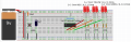
I think it should be doable with just a 4017, so i've tried to translate this schematic to a breadboard using Fritzing
http://www.clarvis.co.uk/version2/4017.html
(I haven't received the 4017 yet, it's somewhere on a slow boat between Ebay and my doormat, so this is a dry run)

Can you help me check my schema?
I'm especially worried about well.. everything?
(the pinning of the 4017, the button, the 4leds in series, the voltage needed)

And even if this works... what happens the 4th time you press a button? there is nothing wired there, so do i need to press it 6 times for it to start at Green again? It would be most awesome if it would be red->yellow->green->off->start at red again.


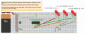
I've added a screenshot, the .fzz fritzing file (renamed to .txt), and for your convenience a link to the pinout of the 4017:
http://zleap.net/wp-content/uploads/2014/02/CD4017-Pin-Diagram.jpg
 

Attachments

djsfantasi

Joined Apr 11, 2010
9,160
You are on the right track. It's do-able but you need a little more work. I see four problems right away.

1) You will need separate resistors for each series LED string. Each color draws a different current

2) You may not have enough voltage to drive four LEDs. Four green LEDs drops 11.2V. More than your 9V supply. The others at their high end will also require more than you have. You will need a driver, which maybe as simple as a BJT transistor and base resistor.

3) As mentioned in the article you link to, you will have to debounce the switch. It's not difficult. You can Google a solution.

4) As you keep teasing the switch after the last indication, you will have to cycle through counts 3-9 to get to the first indication. That is what reset is for. Let's say zero is green, one is yellow and two is red. Then when you press the button and the counter advanced to four, take that output Nd feed it into the reset. Thus three ends up back at zero.
 

Thread Starter

koesper

Joined Mar 18, 2014
6
Thanks guys! I'll rework it later tonight!
The reset is a quick fix, but the debouncing will take some research :D

Also, i'll recalculate my LEDs, because indeed... 9 volt wont cut it...
According to http://led.linear1.org/led.wiz I could do it with 2 paralel series of 2 leds+resistor, so i'll update my design
 

djsfantasi

Joined Apr 11, 2010
9,160
Thanks guys! I'll rework it later tonight!
The reset is a quick fix, but the debouncing will take some research :D

Also, i'll recalculate my LEDs, because indeed... 9 volt wont cut it...
According to http://led.linear1.org/led.wiz I could do it with 2 paralel series of 2 leds+resistor, so i'll update my design
The better way is two parallel strings with TWO resistors. One for each series string. FYI.
 

Thread Starter

koesper

Joined Mar 18, 2014
6
Allright! Thanks again for all the input!
This is what I ended up with:

I've added the reset and moved the outputs one higher (Red = Q1, Yellow = Q2, Green = Q3, Reset on Q4)

The fine art of debouncing is a new mystery to me, but I used:
7v high logic level
9v final voltage
50ms debounce time
1uF capacitor
and then the calculator gave me
33K ohm resistance
But these values are definitely not an educated guess... feedback greatly appreciated!

The remaining puzzle is with the LEDS and the voltage and resistance needed.
Am i correct to assume that i can wire each color up in 2 paralel pairs, each pair with 2 leds in series and a resistor?
(where the two resistors for green are lower than the red/yellow ones, because green has a higher forward voltage drop)
I used http://led.linear1.org/led.wiz for the values


How did I do? am I getting closer? Should I ask the Ebay boat to turn around and go grab some more components? :D

Regards from Amsterdam, the Netherlands
Casper
 

Attachments

djsfantasi

Joined Apr 11, 2010
9,160
I hate fritzing diagrams when I am on my phone? Which is practically all of the time. A "real" schematic is easier to interpret. For basic stuff, I use ExpressSCH because it's free.

I don't like how you've wired up the LEDs. It looks like you have 2 LEDs in parallel with one resistor and 2 more LEDs in parallel with their own resistor.

Of course, I am too lazy to follow my own advice? So I describe the circuit in the following paragraph.

From all of the posts, I would have expected to see two groups of ground wired to a resistor wired to the first LEDs cathode, whose anode is wired to the second LEDs cathode, whose anode goes to the appropriate pin on the 4017. Remember I said two groups, so there is an identical series circuit placed IN PARALLEL to the first.

Repeat for each color.
 

crutschow

Joined Mar 14, 2008
34,412
The fine art of debouncing is a new mystery to me, but I used:
7v high logic level
9v final voltage
50ms debounce time
1uF capacitor
and then the calculator gave me
33K ohm resistance
But these values are definitely not an educated guess... feedback greatly appreciated!
The problem with a simple RC debounce circuit is that the rise-time of the pulse is very slow and will not meet the CD4017 requirements as shown below.
This could possibly lead to flaky counter operation.
upload_2017-1-29_11-53-45.png
To minimize that problem, I would use a debounce circuit such as this, which uses a diode (1N4148 or similar) to give a fast rise-time for the clock requirements, but a slow discharge time to ignore any switch bounce:
upload_2017-1-29_11-58-54.png
The SW goes to V+.
For 50ms debounce time, change R1 to 500kΩ.
 
Last edited:

djsfantasi

Joined Apr 11, 2010
9,160
Crutschow beat me to it. Thanks, @crutschow ! There was something bothering me about your debounce circuit and I was double checking some stuff before replying. Nowadays, I do my debouncing primarily in software.

I agree with the previous post.
 

Thread Starter

koesper

Joined Mar 18, 2014
6
Thanks @djsfantasi, @crutschow and @LesJones!

I knew about software debouncing, but have never done it in hardware.
So at least i learned something new today :)

I'll swap out the debouncer for that diode based beauty
And i'll try to write out my circuit with the official notation as well. Rookie mistake :)

I know i could also build this thing with less parts using an arduino, but i always like a challenge! This is more fun for a coder who never gets to play with hardware :)
hopefully i can squeeze in some nerd-time soon, otherwise i'll pick up were we left next weekend!

All the best!
 

Thread Starter

koesper

Joined Mar 18, 2014
6
Hi guys, unfortunately the 'nerd-time' is scarce at the moment... New job and everything...
But I had a few moments to spare, and tried to incorporate the debouncing, and made some visual changes to the LEDs so i hope you see how they are wired.


PS. I hope the ebay-boat arrives soon, so i can try if i get to short out some components :S
 

Attachments

Top