NE555, CD4017, and ULN2004

Thread Starter

Kharn3655

Joined Apr 24, 2025
6
I'm reasonably new to electronics and would be grateful for any input that you could provide.

I'm designing some custom PCBs for installation into some props. They're largely "inspired by" a kit I bought a good few years ago. I've got about 90% of the design done with no problems, but need a little help to get it over the line.

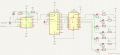
1. Easy part first. Can you run two CD4017s from a single NE555? All of the tutorials I've come across so far deal with daisy chaining 4017s rather than having them both hooked up directly to the 555. It works well enough on the simulation, but are there any reasons what it wouldn't work in real life? As I understand it, the 555 isn't sending anything more than a simple clock pulse out, and since I'm happy to use that same timing on both 4017s I figure that should be ok?

2. LEDs. Most of the LEDs will have their own resistors. There is one set that all run off of a 4017 that I plan on just using a single common resistor though. I figure I can get away with this since only 1 LED will be illuminated at any given time. Am I missing anything with this line of thinking?

3. The big one. ULN2003. I've found very little useful (to a newb) information about this. As I understand it, the purpose in this type of scenario is to have a 4017 connected to the 2003 to allow the LEDs to pull more current than the 4017 is capable of. The simulation shows that I can just about get away with 2 LEDs on a single 4017 output, but that 3 would be too much. What I've managed to understand is that in addition to the higher output voltage and current that it's capable of, it will also amplify the current. Have I understood this correctly, and if so, does this mean that calculating the appropriate resistor values will be more complicated than the usual method?

Schematic attached as a PDF.
 

Attachments

boostbuck

Joined Oct 5, 2017
1,034
Your thinking seems to be correct.

The 2003 will increase the current available to drive LEDs, but the darlington output of that chip will reduce the effective voltage delivered to the LEDs, so the current limiting resistors may need to be reduced in value somewhat for those LEDs to have the same brightness as the directly driven ones.
 

MrChips

Joined Oct 2, 2009
34,628
In order for you to answer these questions on your own in future, I will guide with what is important.

Every output has current and voltage specifications. An output can supply current and it can sink current. You need to examine both cases. When the output has to drive another input or load, you need to look at the current and voltage requirements of the load.

1. Let us examine the datasheet of LMC555 which is what you should be using and not NE555 which draws more current.
When Vs = 5 V, the output can supply 2 mA and it can sink 8 mA. Thus it is better at sinking current, i.e. when the output is LOW.

Now, look at the datasheet of CD4017. The input current is 0.01 mA max. Does that help you to answer question 1?

2. Yes, you can use one resistor. But before you do that, you need to ask the question, how much current will the LED require?
Is the CD4017 output capable of supplying or sinking that much current and still maintain the proper logic level voltage on the output? If you plan on connecting the output of any gate to other gates you should drive the LED off a separate driver in order to not affect the logic level voltages at the output.

3. Read Answer #2. Yes, it is better to use a separate LED driver. It is incorrect to say that the ULN2003 amplifies the current.
Drivers or amplifiers do not amplify current. They have low output impedance so that they are capable of supplying or sinking higher current. So to answer the question more directly, do not drive LEDs from the DC4017. Use a high current driver such as ULN2003. If you are going to use all seven channels of the ULN2003 then you should limit each output to less than 50 mA, which is plenty for a 2 mA LED. Note that the ULN2003 cannot supply current. The output is a current sink.
 

Thread Starter

Kharn3655

Joined Apr 24, 2025
6
Thank you both for your input. You'll have to bear with me if I'm a little slow on the uptake here. I'm self-taught, and the tutorials and guides I've been following have been very broad strokes without much in the way of detailed theory behind them.

1. Let us examine the datasheet of LMC555 which is what you should be using and not NE555 which draws more current.
When Vs = 5 V, the output can supply 2 mA and it can sink 8 mA. Thus it is better at sinking current, i.e. when the output is LOW.
Looking over the datasheet, is this where (attached) you obtain the sinking and sourcing values from? Based on those figures, if extrapolated to a ridiculous degree, you could theoretically have 20 4017s connected based purely on the 4017s current sinking?

Just to make sure as well, have I got that terminology correct? In this instance the 555 is sourcing the current, and the 4017 is sinking it for this particular connection?

2. Yes, you can use one resistor. But before you do that, you need to ask the question, how much current will the LED require?
Is the CD4017 output capable of supplying or sinking that much current and still maintain the proper logic level voltage on the output? If you plan on connecting the output of any gate to other gates you should drive the LED off a separate driver in order to not affect the logic level voltages at the output.
So in reality, I should really always be using some form of driver like a 2003 to run LEDs in this kind of setup?

3. Read Answer #2. Yes, it is better to use a separate LED driver. It is incorrect to say that the ULN2003 amplifies the current.
Drivers or amplifiers do not amplify current. They have low output impedance so that they are capable of supplying or sinking higher current. So to answer the question more directly, do not drive LEDs from the DC4017. Use a high current driver such as ULN2003. If you are going to use all seven channels of the ULN2003 then you should limit each output to less than 50 mA, which is plenty for a 2 mA LED. Note that the ULN2003 cannot supply current. The output is a current sink.
Would any LEDs connected to the 2003 have their appropriate resistance values calculated in the usual manner?


Screenshot 2025-04-26 003323.png
 

boostbuck

Joined Oct 5, 2017
1,034
..... theoretically have 20 4017s connected ....
0.01mA into 2mA is a fan out of 200 not 20, BUT my reading of the several 4000 datasheets gives a MAXIMUM input current about 1uA. In practice the 555 will have no problem driving as many CMOS gates as you like. The symmetry of driving cmos gates means the current is either sourced or sunk, depending on signal change direction.

The max output current of the 4000 series is only a few milliamps, but in practice this can drive a low current LED satisfactorily. A current driver would certainly be needed for any greater demand.

Calculating the resistance for a LED is always the same - the supply voltage less the voltage across the switching device, -edit- minus the LED voltage - divided by the required current for the LED.
 

Attachments

Last edited:

boostbuck

Joined Oct 5, 2017
1,034
..one set that all run off of a 4017 that I plan on just using a single common resistor....
As you have noted in your original post, because the 4017 has only one active high at any time you don't require separate resistors for each pair of LEDs in your circuit. You can use just two LED current-limiting resistors.

1745792998709.png
 
Last edited:

Thread Starter

Kharn3655

Joined Apr 24, 2025
6
Pin 13 on the 4017 goes to ground.
Pin 15 needs a 10K resistor to ground and possibly a 100nf capacitor from pin 15 to +5V as a reset when initially powered ON.
Return C4 on pin 5 of the 555 to ground.
I was having some trouble with the counter running all the way to 10 rather than resetting as intended using a diode connected to pin 10. Disconnecting ground from pin 13 on the breadboard seemed to solve this issue. However, going back to it now it seems that the breadboard is actually faulty somehow. On the simulation the animation was fine with either scenario.

I've seen a couple of variations of a 555 with 4017 setup, some of them didn't have any cap connected to pin5, but the ones that did all had the cap connected to +5V not to ground.
 

Thread Starter

Kharn3655

Joined Apr 24, 2025
6
As you have noted in your original post, because the 4017 has only one active high at any time you don't require separate resistors for each pair of LEDs in your circuit. You can use just two LED current-limiting resistors.

View attachment 348001
My bad! I've jumped between different parts of the design, that particular part does need individual resistors since the LEDs for this part are different colours.
 

MrChips

Joined Oct 2, 2009
34,628
I've seen a couple of variations of a 555 with 4017 setup, some of them didn't have any cap connected to pin5, but the ones that did all had the cap connected to +5V not to ground.
Examine the function of 555-timer pin-5 in the data sheet. It is a control voltage input, similar to pin-6.
The purpose of a capacitor on pin-5 is to reduce HF (high frequency) fluctuations. You can connect the capacitor to Vcc or GND and there will be no difference since Vcc and GND are the same with respect to HF.
 

Thread Starter

Kharn3655

Joined Apr 24, 2025
6
I'm not really seeing a need to reset it to be honest. I do need the lights to flash in a particular sequence, but I don't necessarily need that sequence to start from the same position every time. So if instead of starting at LED 1 and progressing it started at LED 4 it wouldn't be a big deal. Unless there's some other drawback that I haven't realised?
 

sghioto

Joined Dec 31, 2017
8,633
Then pins 15 and 13 need to be grounded.
That sequence not starting at output 0 would only be when first powered ON.
What is the particular sequence you require?
 
Top