Facebook
 Google
 GitHub
 Linkedin
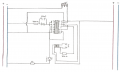
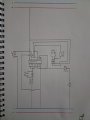
First of all, I must say that I am a novice in circuit design. Let me explain what I want to do: I want to turn on the LEDs sequentially by pressing the button, from output 0 to output 8. and when I get to the 9th exit (even if I press the button) I don't want the queue to go back to the beginning. When I just press the button connected to the reset, the sequence should return to the beginning. The circuit in the picture worked for a while, but then it stopped working. However, when I disconnect the 11th and 14th pins, the circuit works, but the circuit returns to the beginning after the 9th output. So I have two questions: Is there something wrong with the schematic and how do I make the circuit stop when I get to output 9? Finally, I'm sorry English is not very good.

View attachment 338448
View attachment 338448
Attachments
-
 111.4 KB Views: 3