CD4017 16step seq troubleshooting...need help

Thread Starter

Arthuros ntz

Joined Apr 11, 2017
13
Hello community!!
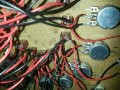
Long story, short. I made a 16 step seq, used two 4017 ic's and a TLC555 as clock. The two 4017 counter are cascaded as datasheet prompts to. My "touch" was that i used only "7" outputs including "0" (bad idea??) for the first 8 steps and output number "8" as a trigger to "activate" the second 4017 via AND gate. The second 4017 starts from output number "1" to "8" ("0" not used)...and "9"as reset to first 4017. And of course i included a diod for each output. So far so good? The result is, that my seq produces multiple steps at the same time i guess, more like a delay. Yes...it goes as it should, each step at a time without jumping and crewing it up (couple of burned leds)...but as soon i connect it to a CV input...i can hear this "echo" thing. I cant really explain what it does, but its not normal. I uploaded a video to show you. Please help!!!

here is a video so you can understand


Supply Vol is 4.5V
The AND gate is sn74hc11n...3 input Ic...
I included bypass caps to components +bulk cap

My multmeter shows that Voltage output of steps (one by one) measured before the diod...is never "0" when step "inactive"...it stays at 0.50~0.70V. (clue?)

This "double output" is persistent <>....how to get rid of it???
Mod edit: snipped profanity.
 

Attachments

Last edited by a moderator:

Thread Starter

Arthuros ntz

Joined Apr 11, 2017
13
I did attach the schematic...but here it is again..without bypass caps...but i have them on board
The result of this project should be a 16 outputs...played in a row...which produce different voltages (via potentiometer).
schm.jpg
 
Last edited:

crutschow

Joined Mar 14, 2008
34,281
That's not a schematic, it's a wiring diagram of the PCB, two quite different things.
A schematic shows the symbols for the functions inside the IC packages.
It's the thing normally used to generate the PCB layout.
 

Thread Starter

Arthuros ntz

Joined Apr 11, 2017
13
I don't really have what you need...because i don't have the software for it...would you like me to "redo" this one..but include somehow the labels on IC's so you could understand which pin does what? (lesson learned)
 

absf

Joined Dec 29, 2010
1,968
I traced out your circuit and it looks something like this .....

tempor.PNG
For the first run the first LED will not be lighted. But subsequent run (after LED16 lighted), it will light normally.

You didn't tie all the unused inputs of the AND gates to ground.

Not sure what's your problem but it simulated in proteus and run OK.

Allen
 

Thread Starter

Arthuros ntz

Joined Apr 11, 2017
13
Thank you for your help...i apologize for the schem. Lesson learned again. I will do as you said. and run a test.

Is it possible that every step is triggered twice..once for HI and one for LOW???
 

absf

Joined Dec 29, 2010
1,968
...but as soon i connect it to a CV input...i can hear this "echo" thing. I cant really explain what it does, but its not normal.
Can you explain more about this CV input? What was it actually? How does this CV affect the running of the lights of the 4017?

What are the volume pots used for ?

Your PCB only tells half of the story....

Allen
 

absf

Joined Dec 29, 2010
1,968
I see that you have more than 16 LEDs. Are you paralleling 3 LED to one 4017 output. And I dont see any current limiting resistors on the LEDs. ARe they directly connected to the o/p of 4017?

Allen
 

ScottWang

Joined Aug 23, 2012
7,397
I see that you have more than 16 LEDs. Are you paralleling 3 LED to one 4017 output. And I dont see any current limiting resistors on the LEDs. ARe they directly connected to the o/p of 4017?

Allen
Here maybe we can be use 3 transistors with some resistors and use 3 diodes with one resistor as 3 input OR gate and use another CD4017 to select one of three 16 leds strings, so when the leds running then it can be light up the first circle, second circle, third circle, and back to the first circle again.
 

Thread Starter

Arthuros ntz

Joined Apr 11, 2017
13
Can you explain more about this CV input? What was it actually? How does this CV affect the running of the lights of the 4017?

What are the volume pots used for ?

Your PCB only tells half of the story....

Allen
CV input is on square wave osc. I mean...cv output of this seq goes to cv input of an osc to produce sound
Pots are used for manipulating voltage=pitch

I see that you have more than 16 LEDs. Are you paralleling 3 LED to one 4017 output. And I dont see any current limiting resistors on the LEDs. ARe they directly connected to the o/p of 4017?


Allen
there are exactly 16 leds...some dead ones..but they are 16
there have a current limiting transistor
There is no paralleling leds
 

Thread Starter

Arthuros ntz

Joined Apr 11, 2017
13
Here maybe we can be use 3 transistors with some resistors and use 3 diodes with one resistor as 3 input OR gate and use another CD4017 to select one of three 16 leds strings, so when the leds running then it can be light up the first circle, second circle, third circle, and back to the first circle again.
Niiiiiiiice...i like what you suggested...i think i understood.
 

absf

Joined Dec 29, 2010
1,968
CV input is on square wave osc. I mean...cv output of this seq goes to cv input of an osc to produce sound
Pots are used for manipulating voltage=pitch
So you are saying that the CV output is connected to the input of an oscillator for producing sounds?
Since the o/p of 4017 goes through 16 diodes, there should no effect on the working of your circuit.

But as people here used to say: "my crystal ball is very blur now and need to send for repair".
If everything is OK, then it should work.....
Could it be a wiring mistake or some dry joints that you didn't notice?

You still need to fill up the blanks in your PCB drawing to clear all your points.

schm_crop.jpg
Where are the wiring of A B C D molex sockets? Are the diodes 1N4148 signal diodes?
Values of pots.....etc etc etc etc

Allen
 

ScottWang

Joined Aug 23, 2012
7,397
If the board didn't works correctly then check the wiring first, and also post the schematic, you can't be only have the diagram of layout and no schematic, where did you get the diagram of layout?
 
Top