Can you help me to understand Op Amps?

MisterBill2

Joined Jan 23, 2018
28,013
National Semiconductor published many volumes of databooks along with application books. Motorola was also good at providing application notes.
The great beauty of applications notes is that they were intended to help engineers make the products work very well, much different than projects designed to sell parts to readers and hope the thing would work. So application notes, definitely including the very old Burr Brown ones, are worth finding. BB is especially good because up until then a whole lot of stuff used tubes, and op-amps were not so very common. So the BB publications were intended to deliver an understanding of the devices.
 

MaxHeadRoom

Joined Jul 18, 2013
30,772
I used to receive example PCT boards populated with some of the latest IC's for review from the major IC manuf.
I still have the one from IR for the IR2110, also the Motorola MC33035 BLDC controller development board.!. :cool:
 

MrAl

Joined Jun 17, 2014
13,765
National Semiconductor published many volumes of databooks along with application books. Motorola was also good at providing application notes.
The great beauty of applications notes is that they were intended to help engineers make the products work very well, much different than projects designed to sell parts to readers and hope the thing would work. So application notes, definitely including the very old Burr Brown ones, are worth finding. BB is especially good because up until then a whole lot of stuff used tubes, and op-amps were not so very common. So the BB publications were intended to deliver an understanding of the devices.
Hi,

I think i still have a National Semiconductor applications handbook with hundreds of app notes from the early1980's or late 1970's.
 

Thread Starter

JosXD

Joined Mar 16, 2022
69
Moving on to the next circuit, the integrator, you might have to understand how capacitors work. I am not sure what you know about them yet. The idea is similar (but again not exactly the same) in that the output does not change immediately for a change in input, but also depends on time. For example, if the input changes by 1v then with the integrator the output STARTS to ramp up (or down), but slowly. As time progresses, the output ramps up more and more, and if the input stays the same it would ramp up to a very high voltage. In a normal circuit, the voltage would be clamped at one of the supply rails, but usually the input changes again and so the output starts to ramp down, then back up, then back down, or else because of feedback it eventually attains some more or less constant value.
If you have more questions on this that's ok i would not be surprised. There is a little more to this because now time is a key factor in the analysis of the integrator circuit.
Thank you MrAI!

I remember an example with super capacitors, a capacitor has a low internal resistance, so you need to add a resistor in series to limit the current but the bigger the resistor the more time it'll take to charge up, so we need to take care of time with capacitors tho.
capacitors.png

But let's see the next complex circuit:
integrator.png
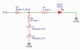
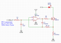
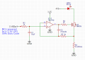
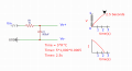
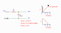
I can see there is a PWM signal that is kind of converted to a steady voltage with the RC low pass filter, duty cycle is 50% so we should expect ~1.65V on the non-inverting input pin, R2 I think is to limit the current to the mosfet's gate, NMOS internal resistance(mOhms) and R3 seems to be our resistor divider to read voltage when the 4V battery voltage drops to tell the Op Amp to compesate that voltage drop on the battery and keep a constant current on the led, but C2 how does it works?

If we say gate to source voltage should be 1V to the mosfet be totally on, the minimum Vo should be >= 1, so if we want that circuit to work out Vo should always > than voltage across RF? and the capacitor defines at what interval it will update the negative feedback?

The "Schematics for Free" website has a number of those applications articles available, and is a reliable site.
Thank you MisterBill2, will check those schematics!
 

Attachments

WBahn

Joined Mar 31, 2012
33,075
Guys, now I would like to get to more into complicated Op Amps mode like the Integrator Op Amp which uses a capacitor, what do you recommend me to start with?
Is it safe to say that you understand the mathematical concepts of integration and differentiation?
 

Thread Starter

JosXD

Joined Mar 16, 2022
69
Is it safe to say that you understand the mathematical concepts of integration and differentiation?
Nope gonna check them right now!

In the university we did Integral Equations, but it was like 5 years ago, I haven't pratice since then, so I don't remember them.
 

WBahn

Joined Mar 31, 2012
33,075
Nope gonna check them right now!

In the university we did Integral Equations, but it was like 5 years ago, I haven't pratice since then, so I don't remember them.
You definitely need to do that. It's going to be very difficult to understand and analyze an opamp that does integration if you don't have a decent understanding of what integration is.

And it really is understanding what integration and differentiation are, not just being able to follow a bunch of rules and steps for manipulating equations that involve them, so make that the focus of your review.
 

MrAl

Joined Jun 17, 2014
13,765
Thank you MrAI!

I remember an example with super capacitors, a capacitor has a low internal resistance, so you need to add a resistor in series to limit the current but the bigger the resistor the more time it'll take to charge up, so we need to take care of time with capacitors tho.
View attachment 296148

But let's see the next complex circuit:
View attachment 296152
I can see there is a PWM signal that is kind of converted to a steady voltage with the RC low pass filter, duty cycle is 50% so we should expect ~1.65V on the non-inverting input pin, R2 I think is to limit the current to the mosfet's gate, NMOS internal resistance(mOhms) and R3 seems to be our resistor divider to read voltage when the 4V battery voltage drops to tell the Op Amp to compesate that voltage drop on the battery and keep a constant current on the led, but C2 how does it works?

If we say gate to source voltage should be 1V to the mosfet be totally on, the minimum Vo should be >= 1, so if we want that circuit to work out Vo should always > than voltage across RF? and the capacitor defines at what interval it will update the negative feedback?


Thank you MisterBill2, will check those schematics!

Hello again,

Why are you jumping to more complicated circuits already?
I am not sure what you know about these yet though, but shouldn't you be looking at a simpler circuit first?

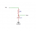
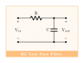
The circuit shown in the attachment is just a simple R and C circuit, where Vin is a constant voltage like 10v and Vout is taken from across the capacitor.

The circuit with the op amp is much more complicated and contains feedback and feedback requires some other theory besides that which is about capacitors, and for a circuit with a transistor and other components too you really have to start to use a more general circuit analysis technique like Nodal Analysis or something like that. That's not too hard to learn though.
 

Attachments

SamR

Joined Mar 19, 2019
5,526
This is just one source. I simply entered National Semiconductor in the search field @ PDF Drive - Search and download PDF files for free. Amazing what you can find on the Net. I had to do "Due Diligence" and document Y2K certifications (after surveying and cataloging ALL plantwide electronics devices) for our plant and did quite a bit of online searching back then.
1686495338072.png
These are just a few there. I lost count after about a dozen plus although some might be duplicates. Many other sources out there with PDF files as well.
 
Last edited:

Thread Starter

JosXD

Joined Mar 16, 2022
69
Hi mates, sorry for the late reply, I've had a lot of work.

You're right I should go slowly.

My understanding about capacitors right now is very limited, for example I know that as the voltage is increasing the current decreases, have seen some formulas for calculate how much will take to charge and discharge, or discharge at certain voltage.

It will charge ~V source and it will discharge dependly on the load when source is off.

In the case of the RC low pass filter with a pwm signal, I think I read something about reactance and ripple voltage, but first I would like to think about the process in a graphical way, I will try think easier with a 10hz pwm.

About a RC LPF with AC signals that's harder because they have negative voltage at some point, that make me think the capacitor sometimes will have V+ and sometimes V-.

RC HPF I have no idea yet.
 

MrChips

Joined Oct 2, 2009
35,022
There are two ways of looking at RC circuits, in the time domain and in the frequency domain. Do one at a time.

Let us look at the time domain first.
We want to draw a graph of Vout over time.
Don’t worry about polarity for now.
Don’t worry about PWM input.

Start with Vin = 0V
What happens when Vin is stepped to 1V?
 

WBahn

Joined Mar 31, 2012
33,075
What is the level of your math background, as that will dictate how you interact with these concepts. Do you have any calculus background?

Your basic understanding of capacitors has some serious flaws in it. You say that you know that as the voltage increases the current decreases. This is not true, but stems from certain situations in which this behavior is exhibited because of indirect factors.

The basic governing equation for a capacitor is

Q = C·V

Q is the charge differential stored on the capacitor.
C is the capacitance of the device
V is the voltage across the capacitor

Current, I, is the rate at which the charge is changing. This is most easily expressed using calculus, but there are other ways and so I will refrain until we have a sense of where your math sits.
 

MrAl

Joined Jun 17, 2014
13,765
Hi mates, sorry for the late reply, I've had a lot of work.

You're right I should go slowly.

My understanding about capacitors right now is very limited, for example I know that as the voltage is increasing the current decreases, have seen some formulas for calculate how much will take to charge and discharge, or discharge at certain voltage.

It will charge ~V source and it will discharge dependly on the load when source is off.

In the case of the RC low pass filter with a pwm signal, I think I read something about reactance and ripple voltage, but first I would like to think about the process in a graphical way, I will try think easier with a 10hz pwm.

About a RC LPF with AC signals that's harder because they have negative voltage at some point, that make me think the capacitor sometimes will have V+ and sometimes V-.

RC HPF I have no idea yet.
Hello there,

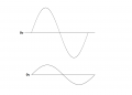
Just for that last sentence, the input would be AC also and as you probably know sinusoidal AC signals usually go positive by some amount called the "peak" or "positive peak" and that is for the first half cycle, then they go negative for the second half cycle. An RC LPF will react to that with plus and minus signals too, so yes, the capacitor voltage in the case of a regular sinusoidal AC voltage, will go plus and minus.

In the attachment the top sine wave could be the input to the RC LPF, and the bottom wave could be the output, which is reduced in amplitude due to the effect of the RC filtering action. We can see a sine wave input and that leads to a sine wave output. The only thing that changes is the amplitude.
 

Attachments

Thread Starter

JosXD

Joined Mar 16, 2022
69
Let us look at the time domain first.

We want to draw a graph of Vout over time.

Start with Vin = 0V

What happens when Vin is stepped to 1V?
Friend do you mean something like the following image?capacitorsx.png

In all the examples I have seen the line looks like a curve, what's the reason it doesn't look like a straight line, 'cuz time resolution in a graph or it's due the charateristics of a capacitor like if its behaivor is different at every level of voltage during its charge?

Your basic understanding of capacitors has some serious flaws in it. You say that you know that as the voltage increases the current decreases. This is not true, but stems from certain situations in which this behavior is exhibited because of indirect factors.
Yes friend I could be wrong, that's what I saw in a video of a guy that explained caps in an easy way, like if it was an introduction for benignners.

In the attachment the top sine wave could be the input to the RC LPF, and the bottom wave could be the output, which is reduced in amplitude due to the effect of the RC filtering action. We can see a sine wave input and that leads to a sine wave output. The only thing that changes is the amplitude.
Amplitude, peaks, thanks friend, let's say the first half cycle is positive, when the second half hits(negative), the positive charge in the cap will be discharged towards the signal(Vin)?

In a PWM, the time that the signal is High(ON or 1) is known as "Width", and + the Low time is known as "Period", or Period could be also the time from one High to the next High, is that right?
 

WBahn

Joined Mar 31, 2012
33,075
View attachment 297158

In all the examples I have seen the line looks like a curve, what's the reason it doesn't look like a straight line, 'cuz time resolution in a graph or it's due the charateristics of a capacitor like if its behaivor is different at every level of voltage during its charge?
It's not that the characteristics of the capacitor are changing -- they aren't. It's really nothing more than Ohm's Law and the resistor.

The sum of the voltage across the capacitor, Vc, and across the resistor, Vr, must equal the applied voltage, Vin.

Vin = Vc + Vr.

When the capacitor starts out discharged, there is no voltage across it. So, initially, Vc = 0 and Vr = Vin. That means that the initial current in the resistor, Ir, is simply Vin/R.

Since the capacitor and the resistor are in series, this is also the current in the capacitor, Ic.

Remember that the relationship between charge and voltage for a capacitor is

Q = C·V

Current is just how much charge is flowing per unit time, so

dQ = I·dt

If you aren't comfortable with calculus and differentials, you can think of this as being "delta-Q", meaning a small change in Q, and "delta-t", the corresponding small change in time.

So, after this small increment of time, the new charge on the capacitor, Qc, is whatever it was at the start of the time interval, Qo, plus the change in charge.

Qc = Qo + dQ = Qo + Ic·dt

The voltage on the capacitor is therefore

Vc = (Qo + Ic·dt) / C = (Qo/C) + (Ic/C)·dt

The last term represents how much the voltage on the capacitor changed over this small time increment. As you can see, the higher the current, the more the voltage change.

However, as soon as the voltage changed on the capacitor, the voltage on the resistor goes down because the sum of the two still has to equal Vin, which isn't changing.

So, the more the capacitor charges, the smaller the voltage across the resistor and therefore the smaller the current in the resistor (and the capacitor), and therefore the slower the capacitor voltage rises.


Vin = Vc + Vr.
 

MrChips

Joined Oct 2, 2009
35,022
@WBahn has described the math for a capacitor C being charged by a voltage Vin through a resistor R.
I am going to do the same thing in a direct and simple way (though laborious). Get out some paper and pencil.
1687834688375.png

In order to simplify things, we will make R = 1Ω, C = 1F and Vin = 1V.
The voltage across the resistor is Vr and the voltage across the capacitor is Vc.
Vr + Vc = Vin.
Current through the resistor is I = Vr / R = (Vin - Vc) / R
Total charge on the capacitor is Qc = Vc x C

Our starting point is with the capacitor fully discharged, Qc = 0, Vc = 0.

Time = 0
Qc = 0, Vc = 0, I = Vr/R = (Vin - Vc)/R = 1A
We calculate the current I, the charge flowing to the capacitor, and the voltage on the capacitor after every 0.1 seconds

Time = 0.1s
Charge flowing = Q = I x 0.1s = 0.1 coulombs
Total charge = Qc = 0.1 coulombs
Vc = Qc / C = 0.1V
New current I = Vr/R = (Vin - Vc)/R = 0.9A

Time = 0.2s
Charge flowing = Q = I x 0.1s = 0.09C
Total charge = Qc = 0.1 + 0.09 = 0.19C
Vc = Qc / C = 0.19V
New current I = (Vin -Vc)/R = 0.81A

Time = 0.3s

Keep repeating this calculation every 0.1 second.
You will notice the current I is decreasing while the voltage Vc is increasing.
Plot the current I versus time.
Plot the voltage Vc versus time.
You will observe that neither follow straight lines.

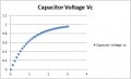
If you do this calculation ten times, i.e. for 1 second, you will observe that Vc reaches about 0.6V.
After about 2 seconds, Vc is about 0.85V.

RC charge curve.jpg

The voltage Vc on the capacitor takes a very long time to ever reach 1V.
In theory, it never reaches 1V because the current through the resistor never reaches zero.

(Note that the above analysis is a crude approximation because we used time increments of 0.1s. For more accurate results we need to choose smaller time steps such as 1ms or 1μs. For this, it would be better to use a spread sheet.)
 

Thread Starter

JosXD

Joined Mar 16, 2022
69
It's not that the characteristics of the capacitor are changing -- they aren't. It's really nothing more than Ohm's Law and the resistor.
@WBahn has described the math for a capacitor C being charged by a voltage Vin through a resistor R.

I am going to do the same thing in a direct and simple way (though laborious). Get out some paper and pencil.
Friends those explanations are Gold!

Much more deeper than the video I saw, where just explain the time it took from 0 to the maximum V, and you explained very detailed how it changes the charge of a cap.

I'm going to make some excersices with that info.

About the curve on a graph, If I just make 3 points, at 0v, 0.5v and 1v then I draw a line between them, won't be smooth and not accurate either, an oscilloscope makes a smooth curve (or almost) because of its refresh rate, right?
 
Top