Can you help me to understand Op Amps?

Thread Starter

JosXD

Joined Mar 16, 2022
69
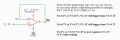
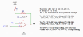
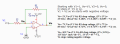
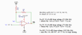
I think you are getting the hang of it. Here is another example with the waveforms. See if you can follow it.
View attachment 295925
Okay that's a sinusoidal wave signal, and they have an amplitude, it's connected to the inverting input so the output signal is inverted plus the gain 30k > 10k 3:1, V+ = VCC(3.3v), V- = (GND).

V2= (3.3v/2) -> V2=1.65
V4= okay this is new for me but I could think that with X ic you are performing that signal, whose amplitude is ±25mV of (3.3v/2) and it can alternate from top to bottom 3 thousand times in 1 second, will alternate each 333µs

inverting input sometimes will be greater than no-inverting, ie when the wave is at top in inverting ~1.675v > 1.65v and when is at bottom inverting ~ 1.625v < 1.65v, but yeah I understand that every mV or microV is important to generate that output signal.

When Vi is 1.675v, Vo = V-(GND) 0V, current from R2 to R1 to Vo will be 41µA, Voltage drop across R2 is 0.41V and R1 is 1.23V, Vi > Vo, so V- will sink 41µA? but can't get how will lower the voltage when V- is 0, wait you said that isn't 0V is ~0V, so that's the way it will lower the output V oooh nice!.

When Vi is 1.625V, Vo = V+(VCC) ~3.3v, now Vo > Vi, and now it seems like current will flow from Vo to Vi but probably the 2 resistor will prevent that, here I'm pretty lost.

I need to pratice a lot more tho, started to learn about Op Amps yesterday kinda frustating.
 
Last edited:

Thread Starter

JosXD

Joined Mar 16, 2022
69
If you add a 3.3V negative supply, then the output can go negative.
Now, since the high gain of the op amp will attempt to keep the voltage difference between pins 3 and 4 very close to zero (which is ground here), the output would go to -2V to conduct the 1mA through R1 and thus R2 to the minus supply.
Remember that there is essentially no current going into or out of pins 3 and 4.
Thanks for your reply Crutschow!

Why 1mA? because Vi - Vo = 1-(-2) = 3V/3000ohms = 1mA?
 

Papabravo

Joined Feb 24, 2006
22,105
Okay that's a sinusoidal wave signal, and they have an amplitude, it's connected to the inverting input so the output signal is inverted plus the gain 30k > 10k 3:1, V+ = VCC(3.3v), V- = (GND).

V2= (3.3v/2) -> V2=1.65
V4= okay this is new for me but I could think that with X ic you are performing that signal, whose amplitude is ±25mV of (3.3v/2) and it can alternate from top to bottom 3 thousand times in 1 second, will alternate each 333µs

inverting input sometimes will be greater than no-inverting, ie when the wave is at top in inverting ~1.675v > 1.65v and when is at bottom inverting ~ 1.625v < 1.65v, but yeah I understand that every mV or microV is important to generate that output signal.

When Vi is 1.675v, Vo = V-(GND) 0V, current from R2 to R1 to Vo will be 41µA, Voltage drop across R2 is 0.41V and R1 is 1.23V, Vi > Vo, so V- will sink 41µA? but can't get how will lower the voltage when V- is 0, wait you said that isn't 0V is ~0V, so that's the way it will lower the output V oooh nice!.

When Vi is 1.625V, Vo = V+(VCC) ~3.3v, now Vo > Vi, and now it seems like current will flow from Vo to Vi but probably the 2 resistor will prevent that, here I'm pretty lost.

I need to pratice a lot more tho, started to learn about Op Amps yesterday kinda frustating.
You got it. V4, the sine wave generator has 3 parameters: DC_OFFSET, Amplitude, & frequency. The curly braces tell the simulator to substitute the parameters that have constant values and are known before the simulation begins.

The .tran {5/f} is telling the simulator to perform a transient analysis for 5 cycles of the sinewave generator. So 5/3000 = 1.667 milliseconds. I have found the use of a simulator very helpful in understanding basic circuits.
 

MrAl

Joined Jun 17, 2014
13,765
Hi,

First of all I'm not a circuit/electrical engineer, I'm a software developer, even tho I learned to desing pcb my knowledge is very basic( battery,resistors,leds), so If you notice I write non sense things you will know why. What I'm doing here? well kind of a hobby.

I've been watching and watching videos about Op Amps and I feel there is a thing I would like to be explained more deeply, I'm going to post 2 pictures, 1 of open loop and another of feedback resistor.

Open loop:
View attachment 295906

In the above diagram there are two cases, one video said that A) If No-inverting input(+) > inverting input(-) (2>1) then positive source is shorted to output Vo=3.3v and B) if no-inverting(+) < inverting (-) (1<2) then gnd or negative souce is shorted to output Vo=0v.

But there is a thing that the video didn't mention and others yes, inverting and no-inverting will have the same Voltage, the question is how? let's take the A) option, after V+ being shorted to Vo the amplifier decreases no-inverting to 1v to equals the inverting, or put both at 0v?


Feedback Resistor:
View attachment 295908

This example costs more to understand, inverting input = 1v and no-inverting input = 0v, how does it flows? first the Op Amp notices inverting > no-inverting then shorts gnd(v-) source to Vo, then Op amp makes inverting input to be 0v to match the no-inverting, but what does the feedback resistor( well the videos says it controls the gain ), but does it flows from R1 to Vo or from Vo to R1?

I could think if flows from R1 to Vo beucase of the 1v input > Vo=0v, it confuses me because both should be 0v. Also could think R1 is to limit current for the Op Amp but that's not the case because the internal resistance in the Op Amp inputs are way to higher that it makes current to be too small that can be considered 0.

I know there are formulas, but I'd like to know if there is a grapich way to explain it easier the part of the feedback resistor when -V = 0v or less.
Hi,

I'll try to help a little too.

There are two main ways of looking at how an op amp works. There are really two basic types but we should probably stick to the voltage feedback op amp first.
In this case, the operation can be explained by a simple math relationship. Here i will use "vn" for the inverting input and "vp" for the non inverting input, and "A" for the internal gain of the op amp, which as you know now can be 100000 or more. It can also be less though for certain special op amps, but this relationship will show how it works for any internal gain, assuming we are just concerned with the DC analysis result.

The simple expression you can start with is this:
Vout=(vp-vn)*A

That is the simple relationship that can allow you to calculate the result for any circuit that contains an op amp. "A" is the internal gain which as you know can be 100000 or more. The limitation on Vout is such that it can only go as high as the positive supply and only as low as the negative supply. If you have a power supply that is +5v and ground (0v), that means the output can only go as high as +5v and as low as 0v, given a rail to rail op amp which is a good way to start thinking about the output range. Later, you'll want to consider limitations with the output also.

Let's start with a lower gain A though. Let's say it is only 100 for now.
This means if you have 1v for vp and exactly 1v for vn, since vp-vn=0 and 0 times A is 0, the output will be zero. The inputs must both be exactly 1v though, considering this is an idea op amp with gain of 100.
Ok, so now raise vp to 1.001 volt and leave vn at exactly 1 volt. When we subtract vp-vn now we get 0.001v, and with the gain of 100, we get 0.1v output.
You can see how simple this is so far.

Now let's increase the gain to 1000. Now vp-vn is still 0.001v, but with the gain of 1000 now the output is 1.0 volts.
If the gain was 10000, the output would be 10 volts, but because the supply voltage is limited to 5v the output would be pinned to 5v. But let's forget about that and say we have a supply that can be very high, like 100000 volts. This i think is not possible in reality, but in theory we can still think about it.
Now when we calculate the output we do get 10 volts.

Again let's increase the gain, up to 100000. Now vp-vn is still 0.001v, and that times 100000 is 100 volts.
So far this should be simple or else you need to study algebra a bit more first.

Now we introduce feedback, with the two resistors as you have shown in your last drawing.
When we get feedback from the output it changes things because now the output is contributing to the inverting input vn. That means some of the voltage will cancel the voltage at vn since there is another resistor in series with vn that acts as the input, and so the voltage at vn is now partly due to the input voltage and partly due to the output voltage. The actual voltage is due to the resistive voltage divider effect, which if you don't know you should look that up or ask about it here also.

Before we get into that though, let's look at the second most basic way to look at an op amp circuit, with the non inverting input vp connected to ground, which is zero volts.

The second way is to consider the current through the two resistors.
Since the vn and vp inputs are considered to be very high impedance (many but not all op amps), that means that vn draws no current. Since it draws no current, that means that any current that flows through the input resistor Ri must also flow through the feedback resistor Rf.
Ok, so if we have 0.001 amps flowing through Ri then we have 0.001 amps through Rf.
Since vp is connected to ground, we can also think of vn as being connected to ground, and this is referred to as a "virtual ground". You can look that up too.
That means that with vn connected to ground the voltage at the input will flow though the input resistor and that will also be the voltage across that resistor. We use Ohm's Law and we know the input current is then Vin/Ri. If Vin is 1v and Ri is 1k, that means the input current is 0.001 amps.
Now as mentioned since the input current is 0.001 amps then the current through the feedback resistor Rf must also be 0.001 amps. Since Rf is connected between 0v and the output voltage Vout, that means that in order to get 0.001 amps through Rf the output must go up to Vout/Rf. So we have this equality:
Vin/Ri=Vout/Rf
This simple equality helps us determine the output voltage.
Ok, so with Vin=1 and Ri=1k, we have 0.001 amps input, and if Rf=2k then Vout must be:
1/1000=Vout/2000
and multiplying both sides by 2000 we have:
(1/1000)*2000=Vout
or:
Vout=2000/1000
so:
Vout=2 volts.

With that simple equality we were able to determine the output voltage.
We can also make a general statement now. Since Vout is equal to Vin*Rf/Rin, the gain of the circuit is:
G=Rf/Rin
and that is how we determine the gain. Now it is easy to calculate the output voltage for any input:
Vout=Vin*G
and G as above so we end up with:
Vout=Vin*Rf/Rin

That is the basic operation.

When we change the circuit a little we do have to take other things into account and we may need a more advanced analysis method, but that is a good way to start.

If anything here does not make any sense just let me know and myself or someone else here will try to clear it up for you.

Just to recap a little here...
We are talking about a voltage feedback op amp.
The circuit is limited to have one op amp and two resistors in a configuration known as an inverting amplifier, as per your last drawing.
 

Ya’akov

Joined Jan 27, 2019
10,278
You are still trying to think in terms of the opamp trying to create a short between the output and one of the supplies.

Forget this.

There is a output driver stage in the opamp that, combined with all of the other circuitry, is trying to make the output equal to the real-high open-loop gain times the differential input voltage. It does this by either sourcing current from the positive supply or sinking current to the negative supply. It sources or sinks just enough to make that output voltage happen. If it isn't sourcing/sinking enough, it will turn the transistors on a bit harder. If it is sourcing/sinking too much, it will turn the transistor on a bit less.
This idea that the opamp is “trying to keep the output in a particular condition” may be anthropomorphic, but as a concept I think it is very powerful. It offers a way to avoid the apparent considering condition of the circuit at any particular time as representing a root cause, and understand why the circuit is currently in that condition as well as others it might evolve into.

Focusing on one condition is like seeing someone trying to clean her paintbrushes and describing it as “putting paintbrushes into a cup of water”, only to be confused later when she runs them under the tap to rinse them because you can’t work out how that is “putting them into a cup of water”.
 

MrAl

Joined Jun 17, 2014
13,765
This idea that the opamp is “trying to keep the output in a particular condition” may be anthropomorphic, but as a concept I think it is very powerful. It offers a way to avoid the apparent considering condition of the circuit at any particular time as representing a root cause, and understand why the circuit is currently in that condition as well as others it might evolve into.

Focusing on one condition is like seeing someone trying to clean her paintbrushes and describing it as “putting paintbrushes into a cup of water”, only to be confused later when she runs them under the tap to rinse them because you can’t work out how that is “putting them into a cup of water”.
Hi,

Am not exactly sure what you are saying there.

I like to describe the dynamics a little differently. I like to think of the output as trying to ramp up (or down) in order to provide the feedback that will cause the inverting input to match the non inverting input. It's sort of like a balance scale, where you put a weight on one side and it slowly moves into balance. Of course the ramping is really referred to as the slewing, but i think ramping is a better term for people just getting into this. In fact, i like to hold off on the dynamics altogether until they can see the operation from a purely static (DC) point of view where the device is already in equilibrium. That way we can say that the inverting input is already the same as the non inverting input.

Op amps are amazing devices. I guess it's really the negative feedback amplifier I think invented by H. S. Black in the early 1900's. It's amazing how negative feedback can provide improved accuracy of the input/output relationship.

Oh I made a mistake when I said I liked your second tenet. I should have said the second line in your signature line, but also your third line as well. It takes a high level of intelligence I think in order to recognize these things.
 

Ya’akov

Joined Jan 27, 2019
10,278
Hi,

Am not exactly sure what you are saying there.

I like to describe the dynamics a little differently. I like to think of the output as trying to ramp up (or down) in order to provide the feedback that will cause the inverting input to match the non inverting input.
Yes, that‘s the idea. The opamp is “trying” to maintain a condition which leads to many possible states. But if you mistake the overall “goal” of the opamp for the “method” of achieving it (how the current flows to achieve the match) you will find different behavior unaccountable.

It’s a general problem of picking a level at which to understand the behavior of a system, that is, identifying the most basic causes, as opposed to mistaking effects for those causes. It happens when fundamentals are not taught along side the practical aspects.

It’s not easy to communicate this idea, and it is, I believe, important but could be a diversion from the core of the thread so maybe there will be another place to discuss it some time.

(Thank you for the kind words re my signature. That is certainly off-topic, though.)
 

Thread Starter

JosXD

Joined Mar 16, 2022
69
Hi guys lot of thanks to everyone who replied this topic!

After watch and read a lot, I kinda decided to found a way and it was like do it in a stepped way/mode, can you confirm if I got it?

First open loop Op Amp as comparator: the inputs itself can't auto adjust to be equal, for that we need feedback but in this example there is not, so if Non-Inverting > inverting then Vo = ~V+, inputs keeps its value because they can't auto adjust, if Non-inverting < inverting then Vo = ~V-, this seems to be the easier.

Closed Loop Op Amp as a Buffer: here is where I applied that kind of stepped way, at the beginning I was like how is possible if we have 1V at Non-inverting and 0V at inverting with V+ = 15v and the result is an output of 1V, then I remembered that probably the voltage won't raise inmmediately in one step from nothing to 15V it should be freaking fast but it takes its time in I don't know nano, pico seconds, so tried this:
opamp_buffer.png

Closed Loop Op Amp Non-Inverting with Negative Feedback: Here was a bit harder because I have even forgotten how to calculate drop voltage across a resistor but no problem I searched for it and finally I understand why the use of a feedback resistor along with another resistor to make a voltage divider which we can use to adjust the desired gain. Example we want a gain of 10, RF/R1+1:

opamp_noninverting.png

Closed Loop Op Amp Inverting with Negative Feedback: this was the worse to understand because I have never tried circuits with negative voltage, I couldn't understand why my maths wasn't correct if is very similar to the non-inverting I think my maths were almost right but I didn't noticed, I watched the trick of the Virtual GND at inverting pin but yes it's confusing because to move current to RF you need the voltage of Vin, that make me think the Virtual GND it's a kind of shorcut (I understood the Virtual GND trick but wanted to understand the normal way), then keep doing the maths 'till I understood, example gain of 10, -RF/R1:
opamp_inverting.png

Have to say that I have doubts in this last example, where I said "Va=V1" at starting, if the Op Amp still haven't decided if Vo = V+ or V-, then Vo isn't connected and we can say there isn't voltage difference between V1 and Vo, so there isn't voltage drop across the resistors yet?

Or probably we can give for sure the loop is closed, so starting Va= 1V/11k= 90uA*1k =0.091V, 1-0.091V = 0.909V, Va shouldn't necessary be equals to V1 at start, because is part of the equation.

And that's it the 1V at V1 it's doing its job trought the resistors divider, that's how it works to get a X gain in this mode.
 

Attachments

Last edited:

MrAl

Joined Jun 17, 2014
13,765
Hi guys lot of thanks to everyone who replied this topic!

After watch and read a lot, I kinda decided to found a way and it was like do it in a stepped way/mode, can you confirm if I got it?

First open loop Op Amp as comparator: the inputs itself can't auto adjust to be equal, for that we need feedback but in this example there is not, so if Non-Inverting > inverting then Vo = ~V+, inputs keeps its value because they can't auto adjust, if Non-inverting < inverting then Vo = ~V-, this seems to be the easier.

Closed Loop Op Amp as a Buffer: here is where I applied that kind of stepped way, at the beginning I was like how is possible if we have 1V at Non-inverting and 0V at inverting with V+ = 15v and the result is an output of 1V, then I remembered that probably the voltage won't raise inmmediately in one step from nothing to 15V it should be freaking fast but it takes its time in I don't know nano, pico seconds, so tried this:
View attachment 296017

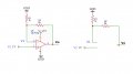
Closed Loop Op Amp Non-Inverting with Negative Feedback: Here was a bit harder because I have even forgotten how to calculate drop voltage across a resistor but no problem I searched for it and finally I understand why the use of a feedback resistor along with another resistor to make a voltage divider which we can use to adjust the desired gain. Example we want a gain of 10, RF/R1+1:

View attachment 296020

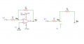
Closed Loop Op Amp Inverting with Negative Feedback: this was the worse to understand because I have never tried circuits with negative voltage, I couldn't understand why my maths wasn't correct if is very similar to the non-inverting I think my maths were almost right but I didn't noticed, I watched the trick of the Virtual GND at inverting pin but yes it's confusing because to move current to RF you need the voltage of Vin, that make me think the Virtual GND it's a kind of shorcut (I understood the Virtual GND trick but wanted to understand the normal way), then keep doing the maths 'till I understood, example gain of 10, -RF/R1:
View attachment 296021

Have to say that I have doubts in this last example, where I said "Va=V1" at starting, if the Op Amp still haven't decided if Vo = V+ or V-, then Vo isn't connected and we can say there isn't voltage difference between V1 and Vo, so there isn't voltage drop across the resistors yet?

Or probably we can give for sure the loop is closed, so starting Va= 1V/11k= 90uA*1k =0.091V, 1-0.091V = 0.909V, Va shouldn't necessary be equals to V1 at start, because is part of the equation.

And that's it the 1V at V1 it's doing its job trought the resistors divider, that's how it works to get a X gain in this mode.
Hi,

Yes that is a good way to think about the process the op amp goes through when presented with an input change.

For your inverting op amp circuit, we usually start with Vout=0, and if Vin=2v then with R1=1k and RF=1k (equal resistor values) then the temporary voltage at the inverting input would be 1v, which is the divider voltage at t=0+ (just a very very short time after t=0). Now because there is 1v at the inverting input and 0v at the non inverting input, the output starts to ramp down, becoming more and more negative. Once the voltage divider and the output and input cause the inverting input to be 0v (really very close to 0v) the op amp output starts to stabilize, then becomes a more or less constant value.

The time it takes for the op amp output to rise by a certain amount is called the "slew rate". The slew rate is usually given on the data sheet.

It's interesting to note that there could be overshoot. The output may rise or fall too much and then the op amp will sense that it needs to change direction again. That would be something to think about later.
 

MrChips

Joined Oct 2, 2009
35,018
Congratulations!
You have successfully applied the iterative method of finding a solution.
This only works if the method converges to a solution. And this happens because negative feedback is responsible.

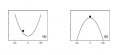
Imagine a marble in a parabolic well as in diagram (a).
ball in well.jpg
If your starting point is with the ball away from the center, you can see that the ball will settle into a stable position at the bottom of the well. Negative feedback causes the ball to find a stable solution.

In (b) with the ball at the top of the hill, the slightest nudge will push the ball over the edge. This is what happens with positive feedback.

Non-inverting op-amp

If we can assume that negative feedback will achieve a stable solution, we can use the steady-state condition to analyze the op-amp circuit.

There are two things to remember in a stable ideal op-amp circuit with negative feedback.
(1) No current flows at both inverting input and non-inverting input.
(2) The voltages at the inverting input and non-inverting input are equal.

By applying these rules, we can eliminate the op-amp in order to analyze the circuit.
Rule (1). No current flows to the inputs of the op-amp. Hence the current in R1 is the same as the current in RF.

Rule (1)
(Vo - V1)/RF = V1/R1

Rule (2)
V1 = V2

Vo = V2 x RF/R1 + V2
Vo = V2 x (RF/R1 + 1)
non-inverting opamp.jpg

Inverting op-amp

We can apply a similar analysis for an inverting op-amp circuit.
inverting opamp.jpg
We apply the same analysis. No current flows to the inputs of the op-amp. Hence the current in R1 must be equal to the current in RF.

Rule (1)
(Vo - Va)/RF = (Va - V1)/R1

Rule (2)
Va = V2

Vo = (V2 - V1) x RF/R1 + V2

In your example, V2 = 0.
Hence we arrive at the inverting op-amp solution:

Vo = -V1 x RF/R1

Note the negative sign in the solution.
 

WBahn

Joined Mar 31, 2012
33,075
Closed Loop Op Amp as a Buffer: here is where I applied that kind of stepped way, at the beginning I was like how is possible if we have 1V at Non-inverting and 0V at inverting with V+ = 15v and the result is an output of 1V, then I remembered that probably the voltage won't raise inmmediately in one step from nothing to 15V it should be freaking fast but it takes its time in I don't know nano, pico seconds, so tried this:
The maximum rate at which the output of an opamp can change is known as it's slew rate. "Slow" opamps, such as the old 741, have slew rates of roughly 1 V/µs, give or take. More modern opamps commonly have slew rates in the range of 20 V/µs. But you can get opamps with slew rates in the 4000 V/µs or even higher.

Have to say that I have doubts in this last example, where I said "Va=V1" at starting, if the Op Amp still haven't decided if Vo = V+ or V-, then Vo isn't connected and we can say there isn't voltage difference between V1 and Vo, so there isn't voltage drop across the resistors yet?
This is still indicative of the thinking that the output is somehow either connected to one of the supply rails.

The output is ALWAYS being actively driven. It is NEVER not connected.

Even if you don't happen to know what the output it, there IS an output. And it doesn't matter what that output happens to be, the negative feedback (if done properly) will result in the output going from whatever it happens to be to whatever voltage is needed in order to make the difference between the two inputs being just the right, very small amount, to produce that output voltage.
 

crutschow

Joined Mar 14, 2008
38,681
Perhaps this will help.
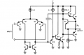
Below is the simplified schematic (the constant-current biasing circuits are not shown) of the common LM324 op amp (which can operate with a single supply down to ground or two supplies),:

Note the transistors Q6 and Q13 controlling the output voltage.
Either one transistor or the other is always conducting, and there is never a direct connection from the output (other than through a transistor) to either the positive rail or the negative rail (which here is ground).

1686245215194.png
 
Last edited:

MrAl

Joined Jun 17, 2014
13,765
Hi guys lot of thanks to everyone who replied this topic!

After watch and read a lot, I kinda decided to found a way and it was like do it in a stepped way/mode, can you confirm if I got it?

First open loop Op Amp as comparator: the inputs itself can't auto adjust to be equal, for that we need feedback but in this example there is not, so if Non-Inverting > inverting then Vo = ~V+, inputs keeps its value because they can't auto adjust, if Non-inverting < inverting then Vo = ~V-, this seems to be the easier.

Closed Loop Op Amp as a Buffer: here is where I applied that kind of stepped way, at the beginning I was like how is possible if we have 1V at Non-inverting and 0V at inverting with V+ = 15v and the result is an output of 1V, then I remembered that probably the voltage won't raise inmmediately in one step from nothing to 15V it should be freaking fast but it takes its time in I don't know nano, pico seconds, so tried this:
View attachment 296017

Closed Loop Op Amp Non-Inverting with Negative Feedback: Here was a bit harder because I have even forgotten how to calculate drop voltage across a resistor but no problem I searched for it and finally I understand why the use of a feedback resistor along with another resistor to make a voltage divider which we can use to adjust the desired gain. Example we want a gain of 10, RF/R1+1:

View attachment 296020

Closed Loop Op Amp Inverting with Negative Feedback: this was the worse to understand because I have never tried circuits with negative voltage, I couldn't understand why my maths wasn't correct if is very similar to the non-inverting I think my maths were almost right but I didn't noticed, I watched the trick of the Virtual GND at inverting pin but yes it's confusing because to move current to RF you need the voltage of Vin, that make me think the Virtual GND it's a kind of shorcut (I understood the Virtual GND trick but wanted to understand the normal way), then keep doing the maths 'till I understood, example gain of 10, -RF/R1:
View attachment 296021

Have to say that I have doubts in this last example, where I said "Va=V1" at starting, if the Op Amp still haven't decided if Vo = V+ or V-, then Vo isn't connected and we can say there isn't voltage difference between V1 and Vo, so there isn't voltage drop across the resistors yet?

Or probably we can give for sure the loop is closed, so starting Va= 1V/11k= 90uA*1k =0.091V, 1-0.091V = 0.909V, Va shouldn't necessary be equals to V1 at start, because is part of the equation.

And that's it the 1V at V1 it's doing its job trought the resistors divider, that's how it works to get a X gain in this mode.
Hello again,

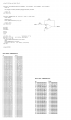
Here is a program that almost exactly simulates what you are talking about.
The only difference is we have to introduce some damping so the output does not swing wildly way up and way down. This damping is found in the function "OpAmp" and is similar to how a real op amp works inside.

The longer list is the list of vn and Vout with more damping and we can see it takes a lot of iterations to settle to a constant value, while with less damping (the shorter list) we can see that it settles down faster at the cost of some ringing near the start. Ringing is the part where it boggles up and down several times before starting to assume some smoother set of values.
 

Attachments

MisterBill2

Joined Jan 23, 2018
27,998
Congratulations!
You have successfully applied the iterative method of finding a solution.
This only works if the method converges to a solution. And this happens because negative feedback is responsible.

Imagine a marble in a parabolic well as in diagram (a).
View attachment 296037
If your starting point is with the ball away from the center, you can see that the ball will settle into a stable position at the bottom of the well. Negative feedback causes the ball to find a stable solution.

In (b) with the ball at the top of the hill, the slightest nudge will push the ball over the edge. This is what happens with positive feedback.

Non-inverting op-amp

If we can assume that negative feedback will achieve a stable solution, we can use the steady-state condition to analyze the op-amp circuit.

There are two things to remember in a stable ideal op-amp circuit with negative feedback.
(1) No current flows at both inverting input and non-inverting input.
(2) The voltages at the inverting input and non-inverting input are equal.

By applying these rules, we can eliminate the op-amp in order to analyze the circuit.
Rule (1). No current flows to the inputs of the op-amp. Hence the current in R1 is the same as the current in RF.

Rule (1)
(Vo - V1)/RF = V1/R1

Rule (2)
V1 = V2

Vo = V2 x RF/R1 + V2
Vo = V2 x (RF/R1 + 1)
View attachment 296038

Inverting op-amp

We can apply a similar analysis for an inverting op-amp circuit.
View attachment 296039
We apply the same analysis. No current flows to the inputs of the op-amp. Hence the current in R1 must be equal to the current in RF.

Rule (1)
(Vo - Va)/RF = (Va - V1)/R1

Rule (2)
Va = V2

Vo = (V2 - V1) x RF/R1 + V2

In your example, V2 = 0.
Hence we arrive at the inverting op-amp solution:

Vo = -V1 x RF/R1

Note the negative sign in the solution.
It would be more correct to not use "GND" as part of the explanations. "COM" for "common" , or even "Supply Common" will be more accurate and less likely to lead to a misunderstanding.. And actually showing the common connections would be even clearer. Just because some understand does not mean that a beginner will understand what is implied.
 

Thread Starter

JosXD

Joined Mar 16, 2022
69
Congratulations!
You have successfully applied the iterative method of finding a solution.
If your starting point is with the ball away from the center, you can see that the ball will settle into a stable position at the bottom of the well. Negative feedback causes the ball to find a stable solution.
In (b) with the ball at the top of the hill, the slightest nudge will push the ball over the edge. This is what happens with positive feedback.
Thank you MrChips for the examples, now that I know the workflow of the simplest Op Amps, I think I can use the formulas directly.

Hi,
Yes that is a good way to think about the process the op amp goes through when presented with an input change.
The time it takes for the op amp output to rise by a certain amount is called the "slew rate". The slew rate is usually given on the data sheet.
It's interesting to note that there could be overshoot. The output may rise or fall too much and then the op amp will sense that it needs to change direction again. That would be something to think about later.

Here is a program that almost exactly simulates what you are talking about.
The only difference is we have to introduce some damping so the output does not swing wildly way up and way down. This damping is found in the function "OpAmp" and is similar to how a real op amp works inside.
MrAI thank you! the diference between inputs(inverting and non-inverting) is the damping right?

The output is ALWAYS being actively driven. It is NEVER not connected.
Even if you don't happen to know what the output it, there IS an output. And it doesn't matter what that output happens to be, the negative feedback (if done properly) will result in the output going from whatever it happens to be to whatever voltage is needed in order to make the difference between the two inputs being just the right, very small amount, to produce that output voltage.
WBahn thank you! that info is really helpful.

Perhaps this will help.
Below is the simplified schematic (the constant-current biasing circuits are not shown) of the common LM324 op amp (which can operate with a single supply down to ground or two supplies),:
Note the transistors Q6 and Q13 controlling the output voltage.
Either one transistor or the other is always conducting, and there is never a direct connection from the output (other than through a transistor) to either the positive rail or the negative rail (which here is ground).
Thank you CrutSchow! I got it, the rails aren't shorted, there are transistors.

Guys, now I would like to get to more into complicated Op Amps mode like the Integrator Op Amp which uses a capacitor, what do you recommend me to start with?
 

MrAl

Joined Jun 17, 2014
13,765
MrAI thank you! the diference between inputs(inverting and non-inverting) is the damping right?

Guys, now I would like to get to more into complicated Op Amps mode like the Integrator Op Amp which uses a capacitor, what do you recommend me to start with?
Hello again,

The line is this one:
Vout=(Vdiff*G+Vout*(G-1))/G

and here Vdiff is just the difference in the inputs as you noted earlier too.
The way you were thinking about the op amp is like this:
Vout=Vdiff*G

and that is good too, as long as you assume the op amp does not respond immediately, which is also ok.

The 'damping' comes in with the other term. We can note that
Vout=Viff*G

is still there, but the other parts are there to slow down the response of the op amp because if the difference suddenly jumps up by 1 volt with a gain of 100000 the output would jump up to 100000 volts, which is not right and not the way an op amp really works.
Inside there is circuitry that limits the rate of rise of the output so that it takes TIME to get up to 100000 volts, and by the time it gets up that high, the input has already changed again so it never gets that high it stays within the power supply limits.

In the statement:
Vout=(Vdiff*G+Vout*(G-1))/G

The amplification is still there in the form of Vdiff*G, but now the output (Vout on the left) actually depends on the previous output too (Vout on the right) and it is averaged in with the new Vdiff and this results in a smaller change. Eventually the entire change affects the output but it takes time to get there. In the two listings we can say that for example each line is 1us after the previous line.

The method used in that program is nothing more than a low pass filter, which is similar (although not exactly the same) as how an op amp works.

Moving on to the next circuit, the integrator, you might have to understand how capacitors work. I am not sure what you know about them yet. The idea is similar (but again not exactly the same) in that the output does not change immediately for a change in input, but also depends on time. For example, if the input changes by 1v then with the integrator the output STARTS to ramp up (or down), but slowly. As time progresses, the output ramps up more and more, and if the input stays the same it would ramp up to a very high voltage. In a normal circuit, the voltage would be clamped at one of the supply rails, but usually the input changes again and so the output starts to ramp down, then back up, then back down, or else because of feedback it eventually attains some more or less constant value.
If you have more questions on this that's ok i would not be surprised. There is a little more to this because now time is a key factor in the analysis of the integrator circuit.
 

MisterBill2

Joined Jan 23, 2018
27,998
There are huge collections of op-amp applications notes that have been published by the manufacturers over the years, and those are what I recommend for study. Avoid all of the videos and yoo-tube presentation cartoons because they are usually incorrect at best, and often leave out details.
The "Schematics for Free" website has a number of those applications articles available, and is a reliable site.
 

MaxHeadRoom

Joined Jul 18, 2013
30,772
This little booklet was written in the 1960’s by Burr-Brown company, one of the pioneers in op amps. It spells out the basics very clearly. In the 1970’s I was lucky to rescue a printed version (nobody had dreamt of pdf at that time) from the trash.

https://www.ti.com/lit/an/sboa092b/sboa092b.pdf
I used to pick up the publications by Howard Sams Co, one was the "Unique IC Op-Amp applications" by W.G. Jung.
One source of these old publications is AbeBooks clearing house.
 
Top