Can someone help a complete amateur with LED fading effect please? :-)

Søren

Joined Sep 2, 2006
472
The the magnetic switch is even better! I can imagine it must be more difficult to handle, but I love a challenge. :)
Not to be too disappointing, but reeds aren't exactly challenging, as long as you don't manhandle them and always bend their pins with a pair of pliers between the glass tube and the bend (with a bit of the pin/wire between the pliers and the glass tube), as the tube is fragile and will break if you try to bend them holding the tube.
I'll recommend reading what Meder have to say about it (and then chill a bit afterward, it's not as hard as you might think after reading their article).
http://www.meder.com/precautions4.html#c8183
When you've read that, air your concerns if any and we'll take it from there.


And you are right, what I wouldn't do for the princess of my heart :-D I am already learning things I would never imagine to learn ever in my life. Things I even quite disliked back in school (physics) :)
Yeah, I hear you - it takes interest to learn! Back in middle school, I only really excelled in science class, art class and English (as a foreign language), in almost all other classes I was always getting notes for my parents, that I wasn't focused and just sat staring out the window.
Even math was boring then and these days, I regularly handles math that my different teachers would have given up on ;)
You gotta see a need for it or just be adequately curious, then you'll learn more and learn faster.


[...] The only thing which is not clear is how a transistor works, how do I use it and to be more specific, which one to use. I already know how to calculate resistors, but I have no idea how to calculate a transistor. I understand that I need a transistor in order to transform a lower current into a higher one, powering those 3 LEDs connected in parallel, am I correct?
Yes, you are correct.
The transistor isn't one you'll learn completely in a day or two, as it can be used in many configurations and there's lots of parameters to it, but for your specific purpose (which you should stick to for now), you could imagine it as a valve that can be turned easily and let a huge pressure through.

A small current through the base-emitter part will open for a current of 100 to 800 times that through the collector-emitter part with a BC547 (depending on the suffix, A, B or C, where C has the highest current gain).

The BC547B is the most used all-round small signal transistor in Europe. Giorgos specifies a BC548, which is almost the same, although specified to 30V max, where the BC547 can handle up to 50V (and BC546 goes up to 80V). At 6V any of them will do.
When no suffix is used, it's common to go with suffix B (which most transistor without suffix marking really are).

I think BTW. that you should keep to the simple version for starters, this is not about making a killer circuit and I'm sure that your princess will be joyed, whether it's perfect or have a slight delay - she'll appreciate it (and you) for the time you took making it and learning how to make it :)

If you get the base version working in a short time, you could consider the slightly more involved version (you might wanna get all the components in one go though).

I'm not sure why Giorgos selected the transistors he did, perhaps it was just what he had at the time he made it, but for Q2 (in the extended circuit), I'd use a BC557 (the PNP version of BC547) and perhaps a BC337 (the NPN version of BC327), as it's a driver, able to handle 6 times the current of a BC547.

I check'd (almost no pun intended, doesn't really work in writing ;)) at GM and this is what I'd recommend:
http://www.gmelectronic.com/bipolar-transistor-bc557c-to92-p210-039
http://www.gmelectronic.com/bipolar-transistor-bc337-40-to92-p210-019
They're both the highest gain binning and for strange reasons a bit cheaper than the more moderate gain types.
Get a couple of each, if your budget allow, then it's not catastrophic if you burn one and they'll be good for little experiments too.


As you told me that the voltage rating is more about how much the part can handle and not to which kind of current it is assigned to, I am guessing that it is the same with transistor? Maybe the only thing I need to choose correctly and specificaly here are the resistors at this point?
As mentioned, there's several parameters to know, to select something that works. Current gain is important in your project and so is max. current, but if you just go with what I suggested, you're in the green and you can learn a bit at a time on transistors - to give you an idea of how complex it is, I know a guy who took his final engineering exam by discussing a single small signal transistor with all it's parameters (and he passed with flying colors).

If you please could give me any guidance, I would really appreciate it so much! And especially with the reed switch solution. I found the local shop have lower voltage ones too, but they are much more expensive: http://www.gmelectronic.com/reed-magnetic-sensor-ka-80-p634-530 However, they have all kinds and they are all in stock, so I can get them quite easily.
The one I linked to is from GM too and it's better and only a third the price. The reason that the one you found is expensive is the size, it's one of the smallest reeds available at only 5mm (it's the length of the glass tube itself), while the one I linked is 14mm.

While I have a specific project for 5mm reeds (or smaller if I can find them), they're a wee bit fiddly to handle due to their small size, so you really should go with the 14mm - they have 5 times the current rating as well and you have plenty of room for the 14mm version (which is only 2.2mm in diameter).

I'll take a hard look at the schematic tomorrow and if I change anything, I'll draw you a new one. I assume you will solder it up on a matrix board like this(?):
http://www.gmelectronic.com/universal-joint-160x100-rm-2-54-belt-joints-p661-048
And if so, I'll make you a layout and base it on components from GM.
I can post some photos on the reed and how to wire it up if that would help.

For experimenting, you might consider getting one of the following two solderless breadboards:
http://www.gmelectronic.com/breadboard-zy-60-p661-137
http://www.gmelectronic.com/building-plate-for-breadboard-zy-170-w-p661-138
(or you could go for a more expensive model, GM has several sizes).

Oh, not to forget... What kind of fade in/out time do you imagine?
 

Thread Starter

Vlk

Joined Apr 17, 2015
26
Not to be too disappointing, but reeds aren't exactly challenging, as long as you don't manhandle them and always bend their pins with a pair of pliers between the glass tube and the bend (with a bit of the pin/wire between the pliers and the glass tube), as the tube is fragile and will break if you try to bend them holding the tube.
I'll recommend reading what Meder have to say about it (and then chill a bit afterward, it's not as hard as you might think after reading their article).
http://www.meder.com/precautions4.html#c8183
When you've read that, air your concerns if any and we'll take it from there.


Yeah, I hear you - it takes interest to learn! Back in middle school, I only really excelled in science class, art class and English (as a foreign language), in almost all other classes I was always getting notes for my parents, that I wasn't focused and just sat staring out the window.
Even math was boring then and these days, I regularly handles math that my different teachers would have given up on ;)
You gotta see a need for it or just be adequately curious, then you'll learn more and learn faster.


Yes, you are correct.
The transistor isn't one you'll learn completely in a day or two, as it can be used in many configurations and there's lots of parameters to it, but for your specific purpose (which you should stick to for now), you could imagine it as a valve that can be turned easily and let a huge pressure through.

A small current through the base-emitter part will open for a current of 100 to 800 times that through the collector-emitter part with a BC547 (depending on the suffix, A, B or C, where C has the highest current gain).

The BC547B is the most used all-round small signal transistor in Europe. Giorgos specifies a BC548, which is almost the same, although specified to 30V max, where the BC547 can handle up to 50V (and BC546 goes up to 80V). At 6V any of them will do.
When no suffix is used, it's common to go with suffix B (which most transistor without suffix marking really are).

I think BTW. that you should keep to the simple version for starters, this is not about making a killer circuit and I'm sure that your princess will be joyed, whether it's perfect or have a slight delay - she'll appreciate it (and you) for the time you took making it and learning how to make it :)

If you get the base version working in a short time, you could consider the slightly more involved version (you might wanna get all the components in one go though).

I'm not sure why Giorgos selected the transistors he did, perhaps it was just what he had at the time he made it, but for Q2 (in the extended circuit), I'd use a BC557 (the PNP version of BC547) and perhaps a BC337 (the NPN version of BC327), as it's a driver, able to handle 6 times the current of a BC547.

I check'd (almost no pun intended, doesn't really work in writing ;)) at GM and this is what I'd recommend:
http://www.gmelectronic.com/bipolar-transistor-bc557c-to92-p210-039
http://www.gmelectronic.com/bipolar-transistor-bc337-40-to92-p210-019
They're both the highest gain binning and for strange reasons a bit cheaper than the more moderate gain types.
Get a couple of each, if your budget allow, then it's not catastrophic if you burn one and they'll be good for little experiments too.


As mentioned, there's several parameters to know, to select something that works. Current gain is important in your project and so is max. current, but if you just go with what I suggested, you're in the green and you can learn a bit at a time on transistors - to give you an idea of how complex it is, I know a guy who took his final engineering exam by discussing a single small signal transistor with all it's parameters (and he passed with flying colors).


The one I linked to is from GM too and it's better and only a third the price. The reason that the one you found is expensive is the size, it's one of the smallest reeds available at only 5mm (it's the length of the glass tube itself), while the one I linked is 14mm.

While I have a specific project for 5mm reeds (or smaller if I can find them), they're a wee bit fiddly to handle due to their small size, so you really should go with the 14mm - they have 5 times the current rating as well and you have plenty of room for the 14mm version (which is only 2.2mm in diameter).

I'll take a hard look at the schematic tomorrow and if I change anything, I'll draw you a new one. I assume you will solder it up on a matrix board like this(?):
http://www.gmelectronic.com/universal-joint-160x100-rm-2-54-belt-joints-p661-048
And if so, I'll make you a layout and base it on components from GM.
I can post some photos on the reed and how to wire it up if that would help.

For experimenting, you might consider getting one of the following two solderless breadboards:
http://www.gmelectronic.com/breadboard-zy-60-p661-137
http://www.gmelectronic.com/building-plate-for-breadboard-zy-170-w-p661-138
(or you could go for a more expensive model, GM has several sizes).

Oh, not to forget... What kind of fade in/out time do you imagine?
Thank you very much for your fantastic answer! This is really amazingly helpful!

I don't mind that the reeds are not challenging. :)) It just sounds like much more sophisticated solution and that is what I definitely like the most. :)
I've read through the Meder's precautions and I can imagine that the handling must be quite tricky, but now I know what to watch out for.

Oh I wish I could understand math as you do! Oh, I sucked so much at math.. I think I was literally the worst in my class. My brain just couldn't handle it. It was also mainly because I had zero interest in learning the subject. I just found it non-important for my life. And here I am, needing it (but actually for the first time of my life... :-D) to create a gift for someone. What a crazy twist of fate. :))

I've read something about the transitors and learned a little bit how they work. It is still kind of a science for me how to connect them in the circuit to make them work properly though, I just don't get that yet. :) But thank you for shining some new light on them for me!

You are right, it is not about making a killer circuit. :) It is just about to make something that will work. :) But if I can do it nicely and neatly at the same time, it would be awesome. :)

Thank you for using my local shop in your search, that is also most helpful! :)

Yes, I learned that you need not to exceed the voltage limit of your parts and that this is the most crucial thing in constructing a circuit. :) So it doesn't matter if I work with 6V and have part that is made up for 220 V. There is just the size concern, as the higher voltage parts are bigger then the ones with lower voltage limits.

You are right, the bigger reed switch makes much more sense. Handling the small one must be quite challenging. :)

Thank you very much for looking into it, you can't imagine how much I appreciate it! Any layouts and photos would be outstanding. :)

I haven't thought about soldering the circuit together, more like just tangle it together and use a hot glue to attach it to the hidden "fake" bottom of the box. I know it's not exactly the best solution.. Maybe I can glue it to the board?

Yes, the testing board is definitely a good idea and 2 eur is not really high price.

And concerning the fade it/fade out time, I thought about 3-5 seconds? I am not sure if 5 seconds is not too long.. I want it to be nicely gradual, but not too long and not too fast. 3 or max 4 seconds might fit into this better.

Again, thank you so much for your help! :)
 

wayneh

Joined Sep 9, 2010
18,133
Not to be too disappointing, but reeds aren't exactly challenging, as long as you don't manhandle them and always bend their pins with a pair of pliers between the glass tube and the bend (with a bit of the pin/wire between the pliers and the glass tube), as the tube is fragile and will break if you try to bend them holding the tube.
Just to be clear, the reed switch I was referring to was an integrated circuit type, not the traditional glass tube type.
 

Thread Starter

Vlk

Joined Apr 17, 2015
26
P.S.: I was thinking that if it would make things easier, I could also go with just 2x LED - the box will be quite small, so I guess the amount of light will be more then sufficient (especially because the box will have just some areas translucent).
 

Søren

Joined Sep 2, 2006
472
Sorry, but I haven't quite finished it - the original circuit is not very good, but I've made a better one - just need component values and then I've made yet another one with more drive, but not quite done either.
I'll get back to you within 16..18 hours I think - gotta sleep now and then fix a few things, but just hang on :)
 

Thread Starter

Vlk

Joined Apr 17, 2015
26
Sorry, but I haven't quite finished it - the original circuit is not very good, but I've made a better one - just need component values and then I've made yet another one with more drive, but not quite done either.
I'll get back to you within 16..18 hours I think - gotta sleep now and then fix a few things, but just hang on :)
Amazing! Thank you very much Soeren! :) I greatly appreciate it!! :))
 

Søren

Joined Sep 2, 2006
472
Hi Vlk,

Took me a while longer than planned to get all the non-related stuff aside.

I made these other circuits and fine tuned them as well as possible, but then it struck me, that I better go back to the original circuit and just improve it, keeping the component count as low as possible.

Here's the resulting circuit:


And to compare how they each do (the simpler of the original ones vs mine), I ran both to compare:
First Giorgos circuit (I had to run it at 14V to drive current through the LEDs):


And the one I made run from 6V:


Both plots are 5s each horizontal square.
The blue curves are the LED current (more or less equivalent to the light they'll put out, the red is the capacitor voltage (around 2.65V max in my circuit) and the yellow is taken just to the right of the switch, to show the triggering, first on then off.

I set the LED current to ~16mA max on 6V, where it has a delay of around a quarter of a second
On 5V, the LEDs see ~12mA max and the delay has increased to a third of a second, while on 4V, the LEDs max current has fallen to 5.2mA and the delay grows to around half a second.
The reason I tested the lower voltages is, that CR2032 has got a high internal resistance and they're specified for currents of 1..2mA max, so they may drop in use.
If you think the current is too low (if it falls to 4V, we can change the circuit a bit - Blue LEDs do appear annoyingly sharp at times, so you might find that you rather wanna dim them some - are you sure she wouldn't prefer red LEDs? :)

The timing can be changed by changing C2 (and capacitors can be mounted in parallel to increase their value (i.e. a 100µF in parallel with a 220µF is equivalent to 320µF and so on, so you can trim the time by having a few different sizes to add).

I'll make you a list with links to the components and the stuff on the reed switch later.


I haven't thought about soldering the circuit together, more like just tangle it together and use a hot glue to attach it to the hidden "fake" bottom of the box. I know it's not exactly the best solution.. Maybe I can glue it to the board?
Is this "Candid Camera" or what? ;)

I take it that this means that you haven't got a soldering iron (no a plumbers iron won't do)?
While it could be build as a "birds nest", it would still be a really good idea to solder the joints.
There do exist things like conductive tape and silver loaded "repair lacquer", but it's fiddly to work with and more important, the components must not be able to move relative to each other.
Let me think about it... Maybe I'll build a "nest" and post the pictures and see if I get any alternative ideas.


Yes, the testing board is definitely a good idea and 2 eur is not really high price.
Even better after I read your last sentences :D
And no, eur 2,- won't even buy you a cup of coffee these days (at least not here).


And concerning the fade it/fade out time, I thought about 3-5 seconds? I am not sure if 5 seconds is not too long.. I want it to be nicely gradual, but not too long and not too fast. 3 or max 4 seconds might fit into this better.
I think I got a useable delay, but it's easy to change via C2
It's likely much easier to just make it (but keep C2 in a spot where it can be tampered with) and then see if you want it longer or shorter.
 

atferrari

Joined Jan 6, 2004
5,020
Regarding the type of LEDs: very recently, helping my (skilled modelist) brother with the lights of a model truck, I "discovered" that modern high efficiency LEDs are definitely worth a try. With less than 1 mA they were shining enough to be visible (and maybe too much).

Thinking that you may want to shine them in a small box, I suggest to consider how strong the light should be for a pleasing effect. Stress is on the pleasing concept.
 

Thread Starter

Vlk

Joined Apr 17, 2015
26
Hi Vlk,

Took me a while longer than planned to get all the non-related stuff aside.

I made these other circuits and fine tuned them as well as possible, but then it struck me, that I better go back to the original circuit and just improve it, keeping the component count as low as possible.

Here's the resulting circuit:


And to compare how they each do (the simpler of the original ones vs mine), I ran both to compare:
First Giorgos circuit (I had to run it at 14V to drive current through the LEDs):


And the one I made run from 6V:


Both plots are 5s each horizontal square.
The blue curves are the LED current (more or less equivalent to the light they'll put out, the red is the capacitor voltage (around 2.65V max in my circuit) and the yellow is taken just to the right of the switch, to show the triggering, first on then off.

I set the LED current to ~16mA max on 6V, where it has a delay of around a quarter of a second
On 5V, the LEDs see ~12mA max and the delay has increased to a third of a second, while on 4V, the LEDs max current has fallen to 5.2mA and the delay grows to around half a second.
The reason I tested the lower voltages is, that CR2032 has got a high internal resistance and they're specified for currents of 1..2mA max, so they may drop in use.
If you think the current is too low (if it falls to 4V, we can change the circuit a bit - Blue LEDs do appear annoyingly sharp at times, so you might find that you rather wanna dim them some - are you sure she wouldn't prefer red LEDs? :)

The timing can be changed by changing C2 (and capacitors can be mounted in parallel to increase their value (i.e. a 100µF in parallel with a 220µF is equivalent to 320µF and so on, so you can trim the time by having a few different sizes to add).

I'll make you a list with links to the components and the stuff on the reed switch later.


Is this "Candid Camera" or what? ;)

I take it that this means that you haven't got a soldering iron (no a plumbers iron won't do)?
While it could be build as a "birds nest", it would still be a really good idea to solder the joints.
There do exist things like conductive tape and silver loaded "repair lacquer", but it's fiddly to work with and more important, the components must not be able to move relative to each other.
Let me think about it... Maybe I'll build a "nest" and post the pictures and see if I get any alternative ideas.


Even better after I read your last sentences :D
And no, eur 2,- won't even buy you a cup of coffee these days (at least not here).


I think I got a useable delay, but it's easy to change via C2
It's likely much easier to just make it (but keep C2 in a spot where it can be tampered with) and then see if you want it longer or shorter.
Thank you very much for taking your time to do this Soeren, you are awesome! :)

I am surprised how many resistors there are! But it looks very neat. :)

The list with the links and stuff on the reed switch would be awesome, thank you! :)

Yes, I don't have soldering iron and the soldering gun. I have just hot glue gun and hot glue. :-D I didn't want to buy more additional stuff, because the soldering gun would be something I would use maybe once in my life. :-D The hot glue can be handy in many occasions, so I bought it also for later use, but soldering gun is not something I would work with.
But I think I could buy some cheap second hand piece - like this one: http://elektro.bazos.cz/inzerat/47066358/mikropajka.php - I think it is the micro one that works on 30-40W - would that be enough? The problem though is that I've never done soldering before. :) Is it something you can mess up quite easily? If I could use the hot glue, I would be happier, but I might as well learn soldering. Every new skill that one can learn is great. :)

You are right, cup of coffee is more expensive. :-D

And concerning the capacitor, the C1 can be left out? It is not necessary in the circuit?

Also, it is interesting that the switch is almost in the middle like this, I wonder how it will work!

And you are right with the LED's. I think it will be quite advantage to dim them a little bit as they might be too sharp. Atferrari has definitely a good point - I would certainly aim for pleasant light rather then the strong one. Unfortunately, I have no idea what pleasant might be in mA. If the full light of the LED is 20 mA, maybe 10 mA might be good? I forgot to tell that I plan to sand the surface of the LED's with fine sandpaper, so the light will be more diffused. I will do the same with the plexiglass I will work with in making the box.
 

Søren

Joined Sep 2, 2006
472
Hi,

I am surprised how many resistors there are! But it looks very neat. :)
The simple explanation:
3 of the resistors (R5..R7) are for current limiting/balancing of the LEDs. Had the LEDs been is series, only one would have been needed.
R1 (plus some influence from R2..R4 and the transistors base-emitter) decides the charge current for C2.
R2 "isolates" C2 somewhat from the base-emitter drop of the transistor.
R3 and R4 helps equalize the charge and discharge time of C2.
R4 is part of the current limit of the LEDs as well.


The list with the links and stuff on the reed switch would be awesome, thank you! :)
Coming up, but probably not before Sunday -


Yes, I don't have soldering iron and the soldering gun. I have just hot glue gun and hot glue. :-D I didn't want to buy more additional stuff, because the soldering gun would be something I would use maybe once in my life. :-D The hot glue can be handy in many occasions, so I bought it also for later use, but soldering gun is not something I would work with.
But I think I could buy some cheap second hand piece - like this one: http://elektro.bazos.cz/inzerat/47066358/mikropajka.php - I think it is the micro one that works on 30-40W - would that be enough? The problem though is that I've never done soldering before. :) Is it something you can mess up quite easily? If I could use the hot glue, I would be happier, but I might as well learn soldering. Every new skill that one can learn is great. :)
That's what you need (definitely not a soldering gun!) and while I know almost nothing about the economy of your country, it does seem cheap, even for a used item - a new similar type would be about 5 times that price here.
And don't worry, you'll soon think of other stuff to build - good for repairs as well :)

You'll need rosin core solder and a tip cleaning "sponge" as well - I'll find such at GM and add to the list.

The glue gun will come in handy too, but for different purposes.

A good way to practice soldering skills is to find some discarded PCB and de-solder some components and re-solder to other pads - let's discuss this more when you've got the soldering iron.


And concerning the capacitor, the C1 can be left out? It is not necessary in the circuit?
You won't know for sure until you made the circuit, but I'd always add it, to rule out potential issues.


Also, it is interesting that the switch is almost in the middle like this, I wonder how it will work!
It isn't in the middle electrically speaking, it connects power to the circuit. The positive wire going to the LEDs are controlled on/off by the transistor and is only carrying a current when the transistor allows = when the reed switch is closed,


And you are right with the LED's. I think it will be quite advantage to dim them a little bit as they might be too sharp. Atferrari has definitely a good point - I would certainly aim for pleasant light rather then the strong one. Unfortunately, I have no idea what pleasant might be in mA. If the full light of the LED is 20 mA, maybe 10 mA might be good? I forgot to tell that I plan to sand the surface of the LED's with fine sandpaper, so the light will be more diffused. I will do the same with the plexiglass I will work with in making the box.
Yes Atferrari is right about the low power LEDs as well, I'll see if GM has got any of those.
It's impossible to judge how much light is needed, when you haven't seen the box, or know how it's supposed to be lit, so best option is test it out and make changes if needed.
I didn't realize that you would make the box in Plexiglass, but if it's the clear type, you'd be able to see all the "magic", unless you paint some of the inside, but that's a thing that only you can decide on..

I'll get back to you with a list and photos :)
 

Søren

Joined Sep 2, 2006
472
Just to be clear, the reed switch I was referring to was an integrated circuit type, not the traditional glass tube type.
Ah, yes, they do come in many disguises. I have one which is just a reed in a small plastic shell, some inside "explosion proof" switches, some in alarm type encapsulation and of course reed relays (where the reed switch can be used with a magnet, if they're not in a steel housing) and some encapsulated like a SIP circuit, but I haven't seen one quite like an integrated circuit alone - While it makes most sense using a reed here (for the zero power consumption), are you sure it isn't a Hall switch?

You probably are, but if not, the pin count will reveal it (reed 2, Hall 3 or 4).
 

wayneh

Joined Sep 9, 2010
18,133
...are you sure it isn't a Hall switch?
No, I'm not. Folks have referred to it as a reed switch but that could just be a misnomer. I halfway recall it had 3 pins but that could be for physical stability.

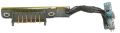
update - Found a picture. The service manual calls it a "sleep switch" and makes no reference to the technology. I believe that 3-pin IC is the sensor.
Screen Shot 2015-04-24 at 7.31.35 PM.png
 
Last edited:

Thread Starter

Vlk

Joined Apr 17, 2015
26
Hi,


The simple explanation:
3 of the resistors (R5..R7) are for current limiting/balancing of the LEDs. Had the LEDs been is series, only one would have been needed.
R1 (plus some influence from R2..R4 and the transistors base-emitter) decides the charge current for C2.
R2 "isolates" C2 somewhat from the base-emitter drop of the transistor.
R3 and R4 helps equalize the charge and discharge time of C2.
R4 is part of the current limit of the LEDs as well.


Coming up, but probably not before Sunday -


That's what you need (definitely not a soldering gun!) and while I know almost nothing about the economy of your country, it does seem cheap, even for a used item - a new similar type would be about 5 times that price here.
And don't worry, you'll soon think of other stuff to build - good for repairs as well :)

You'll need rosin core solder and a tip cleaning "sponge" as well - I'll find such at GM and add to the list.

The glue gun will come in handy too, but for different purposes.

A good way to practice soldering skills is to find some discarded PCB and de-solder some components and re-solder to other pads - let's discuss this more when you've got the soldering iron.


You won't know for sure until you made the circuit, but I'd always add it, to rule out potential issues.


It isn't in the middle electrically speaking, it connects power to the circuit. The positive wire going to the LEDs are controlled on/off by the transistor and is only carrying a current when the transistor allows = when the reed switch is closed,


Yes Atferrari is right about the low power LEDs as well, I'll see if GM has got any of those.
It's impossible to judge how much light is needed, when you haven't seen the box, or know how it's supposed to be lit, so best option is test it out and make changes if needed.
I didn't realize that you would make the box in Plexiglass, but if it's the clear type, you'd be able to see all the "magic", unless you paint some of the inside, but that's a thing that only you can decide on..

I'll get back to you with a list and photos :)
Thank you again for your answer, I am so grateful you are helping me with this! :)

And thanks for explaining the resistors, I understand it now. :)

I will be getting the parts ideally this upcoming week, so sunday is perfect, but anytime in the upcoming week is great. :) There is still a lot of time to get and do everything until the 4.5. :)

It is very cheap - to USD it is about 5 dollars, so I will definitely get it. :) I already wrote to the guy who is selling it - he is even from my town, so I can meet up with him easily. :) So I will learn soldering, I am excited! :-D I watched some videos on Youtube and I can see that it works quite like the hot glue. The tip heats up the soldering iron which you hold in your other hand and you let it drip (or just touch the desired place with it) on the place where you want to solder your part and you stick the part's wire into the stuff and it hardens. And done! It is possible to re-solder anything apparently, heating the place again with the tip and removing the soldered part (or just move it or something like that :) ).

I don't want to complicate things, but I found out that there is a lead-free iron for soldering (this one is cheap and in quite practical design http://www.rr-naradi.cz/cinova-pajka-v-tuzce-pbf-sn-993cu07-1-mm-15-g), but it has smelting temperature higher then the one with lead (around 220°C) - do you think I will be able to solder it with the tool I linked?

So the best way would be to solder all the parts onto the matrix board you linked earlier right? Oh, I hope I will be able to do all this the right way. :) I can see that the soldering takes place on the bottom of the board, not on the top as I initially thought.

Yes, you are right, best way would be to try it and see how it looks like and if the light is pleasant. I will see how it works out when I will be building this on the solderless board.
The box will be made out of hard wood and plexiglass. Some parts would be non-transparent due to the use of wood, but other parts would have nice patterns made from the pure transparent plexiglass, which would be fine sanded and the light will be shining through, diffused. I think it will create a really nice and elegant effect. :)

The box will be about 10 cm long and 5,5 cm wide - will it be enough for the circuit to fit in?

I was thinking if it is possible to make a different fade-out time than the fade-in time? That the fade in would be around 3 sec. and the fade out would be much longer, after the box would be closed and the light would shine through the transparent parts, it would be nice if it could stay in and then go out for little longer. I guess this is something unrealistic right? .-) It is just a thought, it is definitely not necessary. :) I might as well create a nice compromise and make the fade in slightly longer, so the fade out will also be a little longer thus creating the desired effect.
 
Last edited:

Søren

Joined Sep 2, 2006
472
Hi,

First, the promised list of components with links.

R1, 4k7 http://www.gmelectronic.com/rm-4k7-0204-0-4w-1-yageo-p119-132
R2 and R3, 2k7 http://www.gmelectronic.com/rm-2k7-0204-0-4w-1-yageo-p119-079
R4, 27 Ohm http://www.gmelectronic.com/rm-27r-0204-0-4w-1-yageo-p119-078
R5, R6 and R7, 18 Ohm http://www.gmelectronic.com/rm-18r-0204-0-4w-1-yageo-p119-252

C1 and C2, 470 µF http://www.gmelectronic.com/cea-470u-16v-vis-asm-8x18-p123-303
(This is the axial type, as they're lower than radial types, so will be easier to fit).

Q1, BC547-C http://www.gmelectronic.com/bipolar-transistor-bc547c-ammo-p210-129
Better get a spare, just in case :)

LED3, LED4 and LED53, Two options here (sorry about their component numbers, I just realized that I didn't get them renumbered).
3mm blue http://www.gmelectronic.com/led-3mm-blue-1000-30-p518-062
or 5mm blue http://www.gmelectronic.com/led-5mm-blue-300-60-p511-749
The 5mm version may be the better option, as it spreads its light twice as much (and it's gives 18.2% more light).
The 3mm LED will be easier to fit, if the space is limited.

Reed switch http://www.gmelectronic.com/reed-magnetic-sensor-meder-ksk1a66-1020-p634-529
If you haven't got magnets for this (almost any magnet of a suitable size will do), or if you can't find them cheaper locally, get two (2) of these:
http://www.gmelectronic.com/p-mm312-p634-611
(one for actuation and one for reverse biasing the reed switch).

2 pcs. CR2032 coin cells http://www.gmelectronic.com/lithium-battery-cr2032-lithium-vinnic-p542-006
2 pcs. coin cell holders http://www.gmelectronic.com/pcb-mounted-battery-holder-for-cr2032-ch25-2032-p819-121
Like with the magnets, you may be able to by the coin cells locally, perhaps in a 10-pack, if you have a dime store around.

You'll need some wire as well, but you may have that already (discarded electronics is a good source of spare wires btw.), so I didn't put that on the list. Likewise with the solder, we'll take that in my reply to your last post.
 

Søren

Joined Sep 2, 2006
472
Hi,

I will be getting the parts ideally this upcoming week, so sunday is perfect, but anytime in the upcoming week is great. :) There is still a lot of time to get and do everything until the 4.5. :)
Monday it is then ;)


It is very cheap - to USD it is about 5 dollars, so I will definitely get it. :) I already wrote to the guy who is selling it - he is even from my town, so I can meet up with him easily. :) So I will learn soldering, I am excited! :-D I watched some videos on Youtube and I can see that it works quite like the hot glue. The tip heats up the soldering iron which you hold in your other hand and you let it drip (or just touch the desired place with it) on the place where you want to solder your part and you stick the part's wire into the stuff and it hardens. And done! It is possible to re-solder anything apparently, heating the place again with the tip and removing the soldered part (or just move it or something like that :) ).
Go grab it while it's there.
I'm not to keen on comparing it to a glue gun though. In a glue gun you melt the glue and then apply it. In soldering, you heat up the parts (component pin and the pad it solders to) and then you let the heated parts melt the solder - touch the solder tip lightly with the solder before touching the parts, to help spread the heat.
Let's save the gory details until you have the soldering iron and solder.


I don't want to complicate things, but I found out that there is a lead-free iron for soldering (this one is cheap and in quite practical design http://www.rr-naradi.cz/cinova-pajka-v-tuzce-pbf-sn-993cu07-1-mm-15-g), but it has smelting temperature higher then the one with lead (around 220°C) - do you think I will be able to solder it with the tool I linked?
First, using leaded solder won't harm you - the entire purpose of lead free solder is to avoid massive amounts of lead in discarded electronics, which over time will seep into the ground water (as a salt).
Second, it needs a higher temperature than lead based solder and the iron you get will likely not be hot enough for it. Further it's harder to work with and to avoid cold joints. I bought a spool 5..7 years back and I absolutely hated it, so I tossed the spool after a bit of testing (although these days, there's plenty of different unleaded solders, but they're mainly available to the industry).

Electronics are just like an action movie - the more lead the better :D
(but sadly, it burns less rubber)

I'll recommend this: http://www.gmelectronic.com/tin-solder-tin-0-8mm-18g-sn63pb37-p745-011
It's less than a quarter of the price at Conrad, it has got 20% more solder (by weight) and it's o.8mm, rather than 1mm, so even the same weight will result in a longer piece.
The smaller diameter will help you to avoid solder blobs and if you buy it online (not sure if you have a physical shop nearby), getting it all from one place will give a lower shipping cost.

A sponge for wiping the tip (goes into the square(-ish) hole in front of the holder of the soldering iron that you found) is better than moist tissue paper:
http://www.gmelectronic.com/sponge-for-cleaning-tips-proskit-508-351-sp-p731-194

And if you wanna desolder components in a PCB, solder wick is great:
http://www.gmelectronic.com/desoldering-wick-proskit-8pk-031b-p731-323


So the best way would be to solder all the parts onto the matrix board you linked earlier right? Oh, I hope I will be able to do all this the right way. :) I can see that the soldering takes place on the bottom of the board, not on the top as I initially thought.
If you want to go with the board, GM has got this:
http://www.gmelectronic.com/universal-joint-160x100-rm-2-54-belt-joints-p661-048
If you go to a physical shop, you could ask for a smaller size, as this "euro card size" will be enough for several circuits.

With the relatively few components, you could do it birds nest like, as long as you solder each connection - it won't be pretty though ;)

Either way, I'll talk you through it and rest assured, that unless you've got Parkinsons disease or similar, you will get it done right!


Yes, you are right, best way would be to try it and see how it looks like and if the light is pleasant. I will see how it works out when I will be building this on the solderless board.
The box will be made out of hard wood and plexiglass. Some parts would be non-transparent due to the use of wood, but other parts would have nice patterns made from the pure transparent plexiglass, which would be fine sanded and the light will be shining through, diffused. I think it will create a really nice and elegant effect. :)

The box will be about 10 cm long and 5,5 cm wide - will it be enough for the circuit to fit in?
Plenty!
I'll make a layout for the matrix board and then I can tell you the exact size.
I'm sure the box is gonna be nice :)


I was thinking if it is possible to make a different fade-out time than the fade-in time? That the fade in would be around 3 sec. and the fade out would be much longer, after the box would be closed and the light would shine through the transparent parts, it would be nice if it could stay in and then go out for little longer. I guess this is something unrealistic right? .-) It is just a thought, it is definitely not necessary. :) I might as well create a nice compromise and make the fade in slightly longer, so the fade out will also be a little longer thus creating the desired effect.
Oh, had you told this a little sooner, I'd had saved some time :p
Most of the time making the circuit was to cut down the fade out time to make it similar to the fade in.
Just wait with ordering and I'll change the circuit to suit :)
 

Thread Starter

Vlk

Joined Apr 17, 2015
26
Hi,


Monday it is then ;)


Go grab it while it's there.
I'm not to keen on comparing it to a glue gun though. In a glue gun you melt the glue and then apply it. In soldering, you heat up the parts (component pin and the pad it solders to) and then you let the heated parts melt the solder - touch the solder tip lightly with the solder before touching the parts, to help spread the heat.
Let's save the gory details until you have the soldering iron and solder.


First, using leaded solder won't harm you - the entire purpose of lead free solder is to avoid massive amounts of lead in discarded electronics, which over time will seep into the ground water (as a salt).
Second, it needs a higher temperature than lead based solder and the iron you get will likely not be hot enough for it. Further it's harder to work with and to avoid cold joints. I bought a spool 5..7 years back and I absolutely hated it, so I tossed the spool after a bit of testing (although these days, there's plenty of different unleaded solders, but they're mainly available to the industry).

Electronics are just like an action movie - the more lead the better :D
(but sadly, it burns less rubber)

I'll recommend this: http://www.gmelectronic.com/tin-solder-tin-0-8mm-18g-sn63pb37-p745-011
It's less than a quarter of the price at Conrad, it has got 20% more solder (by weight) and it's o.8mm, rather than 1mm, so even the same weight will result in a longer piece.
The smaller diameter will help you to avoid solder blobs and if you buy it online (not sure if you have a physical shop nearby), getting it all from one place will give a lower shipping cost.

A sponge for wiping the tip (goes into the square(-ish) hole in front of the holder of the soldering iron that you found) is better than moist tissue paper:
http://www.gmelectronic.com/sponge-for-cleaning-tips-proskit-508-351-sp-p731-194

And if you wanna desolder components in a PCB, solder wick is great:
http://www.gmelectronic.com/desoldering-wick-proskit-8pk-031b-p731-323


If you want to go with the board, GM has got this:
http://www.gmelectronic.com/universal-joint-160x100-rm-2-54-belt-joints-p661-048
If you go to a physical shop, you could ask for a smaller size, as this "euro card size" will be enough for several circuits.

With the relatively few components, you could do it birds nest like, as long as you solder each connection - it won't be pretty though ;)

Either way, I'll talk you through it and rest assured, that unless you've got Parkinsons disease or similar, you will get it done right!


Plenty!
I'll make a layout for the matrix board and then I can tell you the exact size.
I'm sure the box is gonna be nice :)


Oh, had you told this a little sooner, I'd had saved some time :p
Most of the time making the circuit was to cut down the fade out time to make it similar to the fade in.
Just wait with ordering and I'll change the circuit to suit :)
Thank you so much for your reply and for writing down the list of components!

I will see the person who is selling the soldering machine hopefully in wednesday. :) Thank you for explaining the soldering process, I understand it better now. :) I originally thought it works more like a wax - heating the iron and let it drip on the certain place. Can't wait for the gory details! :-D

I will get the lead one then. :) It is much cheaper too, it is just that I am not a fan of lead - always heard so many bad things about it and I wasn't so excited to work with it, but of course it can't do any harm in such a small project. :) It will definitely make things easier.

Electronic are just like action movie :-D You got me on that one :-D

Concerning the sponge, will any dish cleaning sponge do the job as well? Won't the heat of the tip burn/melt the sponge (even the soldering one?).

I am thinking if I should get the board or not.. But I think I will, even if the sheet is much larger then I need and it is not the cheapest solution. I like the neat/clean job more then use tons of hot glue and create a wild bird's nest. :) The nest just seem much easier to comprehend though, because you connect the components directly to each other and it is much more visually similar to the circuit plans, whereas on matrix board, you have all those designated holes and paths and I am not entirely sure how it works :) But I guess I will figure it out. :)
Only thing which I just realized is that the matrix board has a certain color which might be visible through the fake plexiglass bottom, whereas using the black hot glue would be barely visible I think, as I will be using eben like wood for the box. That is also a thing to consider.. But I might pour the black glue all over the matrix board too (after soldering the parts onto it) and it would be the same thing maybe? :-D

Thank you for reassuring me! :))

Thank you very much for the matrix layout! I think the size of the box should be enough to hold the circuit, at least I hope. :) If not, I can always make it larger. :)

Oh, I am sorry! It just came to me yesterday, when I was trying to visualize the box in my mind (I was also drawing the concept of the box) and I realized, it might be more pleasant to make the fade out time after closing the box longer. It is the moment when you enjoy the light, look at the closed box and then it slowly goes off until it is dark.. It sounds really awesome, so I thought I would ask you. :) I would never imagine it is actually the easier way to do it!

So I will hold the e-shop basket for now. :)

Soeren, thank you so much for all this! I feel so guilty taking so much of your time, but I am really so so grateful for all your help! I wish I could do the same for you with something else you might need and might find useful! I am a graphic designer (and creative guy in general - the box will hold earrings which I will also craft!), so anything concerning graphics, I am all yours! :-D
 

Søren

Joined Sep 2, 2006
472
Hi

Just a quick note...
1 resistor removed and two other resistors changed, so now fade in is ~2.1s and fade out is 18.3s
This is the 10%-90% usually used for rise and fall times, visually they'll be around 3s fade in and 27..28s fade out.

Will that do, or do you want the fade out shorter?

The format on matrix board will be 10cm x 4.5cm as is - the two battery holders take up most of the space

I'll post the slightly changed schematic and the layout tomorrow, but I need a bit of shut-eye first.
 

Thread Starter

Vlk

Joined Apr 17, 2015
26
Hi

Just a quick note...
1 resistor removed and two other resistors changed, so now fade in is ~2.1s and fade out is 18.3s
This is the 10%-90% usually used for rise and fall times, visually they'll be around 3s fade in and 27..28s fade out.

Will that do, or do you want the fade out shorter?

The format on matrix board will be 10cm x 4.5cm as is - the two battery holders take up most of the space

I'll post the slightly changed schematic and the layout tomorrow, but I need a bit of shut-eye first.
Thank you Soeren! If the fade out could be shorter, it would be nice, but only if it won't be too difficult to do it. I would see it ideally around 10-15 seconds of real time?

Perfect, so it will fit the box nicely!

Thank you so much for the schematic and layout!

Just a thing concerning the reed switch - I looked up some informations on the net and I just wanted to be sure if I understand it correctly:

One magnet needs to be bellow the switch, which I will somehow integrate within the base of the box (I can imagine it will have to be in the side part, either left or right, will depend on the circuit) and one magnet, which will be integrated (I guess I will bore a hole for them and hot glue them there) in the lid. The switch will be also hidden in the wood, it will need to be exactly between these two magnets, so I imagine somewhere just below the rim where the base of the box ends. There will be wires going from it, sliding below the fake plexiglass bottom and there will be the circuit, nicely hidden. It will be a little tricky I think, but I have the idea of how it should work in my mind.
Do you think the magnets will also work as a mechanical closing? That they will hold the lid closed?
 

Søren

Joined Sep 2, 2006
472
If the fade out could be shorter, it would be nice, but only if it won't be too difficult to do it. I would see it ideally around 10-15 seconds of real time?
Just changed it to 2.5s in and 12.8s out, by adding back a single resistor.
However, the attached .pdf won't reflect that, but I'll update it tomorrow. Apart from what's in the .pdf, you'll need a 22k resistor:
http://www.gmelectronic.com/ru-22k-0207-0-25w-5-p119-066


Just a thing concerning the reed switch - I looked up some informations on the net and I just wanted to be sure if I understand it correctly:

One magnet needs to be bellow the switch, which I will somehow integrate within the base of the box (I can imagine it will have to be in the side part, either left or right, will depend on the circuit) and one magnet, which will be integrated (I guess I will bore a hole for them and hot glue them there) in the lid. The switch will be also hidden in the wood, it will need to be exactly between these two magnets, so I imagine somewhere just below the rim where the base of the box ends. There will be wires going from it, sliding below the fake plexiglass bottom and there will be the circuit, nicely hidden. It will be a little tricky I think, but I have the idea of how it should work in my mind.
Do you think the magnets will also work as a mechanical closing? That they will hold the lid closed?
The exact position of the magnets, relative to the switch, depends on the strength of the respective magnetic fields, but the reed won't need to be smack dab in the middle.
Different strength magnets can be used and while I have to work the thought a bit, either the lid-magnet can close toward a bit of iron or another magnet, which may then be usable for bias as well... I need to think it through.

If you want to use magnets for closing, the one I linked from GM (AlNiCo magnet) won't do, they're much too weak. They do have a set of 10 magnets from Velleman but the latter describes them as "rating: N35~N45", which is sort of nonsense, as the Nnn describes a set of parameters of a magnet (like strength and high temperature limit) and they don't have such loose specs.

Besides, although neodymium magnets are strong compared to AlNiCo, N35 is about as weak as they come,while N45 is about "medium" - really strong neo's are N5n.
They'd all be OK for your box though, but they're eur 5.07 for 10 at GM, so if you have a cheap thrift store locally, you might be able to pick up a few magnets with attached fridge ugliness much cheaper, or perhaps one of the weighted steel wires, that uses small neo's for attaching postcards and photos to the wire - the ones I've seen had 8..10 magnets in such a "set" - just make sure that you get the strong neodymium types (if they look small for the purpose, they probably are neo's) - there's and endless amount of cheap stuff and toys using them.

The reason to go for neo's is to get the dimension down while keeping a good strength - if you stand a cylindrical magnet on the edge on eg. a table and tip the table a little, a strong magnet will try to only roll a path of east-west (if polarized along its length, i.e. N-S on the plane sides) - that's how strong they are.


I didn't put wire on the list, as you'll likely be able to scoop some up - even a short piece of CAT5 "Ethernet" cable will give you plenty.

The sponge I left out as well, no extreme need for it, as you can use a moist tissue paper or a moist piece of cotton cloth. The sponges are made of cellulose (organic) and must be moist in use, or they won't last long - I use distilled water on them, to make them live longer and stay softer - they're pretty stiff when dry, no matter the water.
By moist I don't mean wet - the moisture only has the purpose of protecting the sponge by a ~100°C vapor barrier. If wet, they'll cool the tip (and shock it a bit) - not good.

You can get cellulose sponges made for several other purposes. Some (most?) sponges for wiping a black board is that type and the cheapest I've found are some oval shaped 1,0..1,5cm thick sponges used for cleaning kitchen and bath - just read on the packet what it's made from. They're a light yellow-beige-ish color.

A plastic foam sponge would die screaming and hurt your soldering tip as well.


BTW. do you shop in GM's physical shop or order online?

Here's the .pdf View attachment LED_Fade_On-Off_2.pdf
 

Søren

Joined Sep 2, 2006
472
Hi Wayneh,

Sorry I didn't catch your post sooner (I really should learn to not just read the latest posts).

No, I'm not. Folks have referred to it as a reed switch but that could just be a misnomer. I halfway recall it had 3 pins but that could be for physical stability.

update - Found a picture. The service manual calls it a "sleep switch" and makes no reference to the technology. I believe that 3-pin IC is the sensor.
View attachment 84595
If you're referring to the SOT-23, I'm pretty sure it's a hall switch. They're usually very resilient, so I'd re-solder the entire board and test connectivity all the way through the connector at the left as a first try, especially if it gets bumped around a lot or dropped.

If you have to replace the hall chip, be aware that they come in different configurations: magnetic pole of the front side (where the markings are) can be either north or south and there's 4 digital types, as well as analog hall sensors. It's important to get the same polarity, pinout and so on.
  • The unipolar type is active when it sees a field of the polarity and strength required, and switches off when the field is removed.
  • The bipolar type is a bit similar to the latch type, although the field levels may be asymmetric and in some cases, they can be brought to function within a single polarity.
  • The latch type turns on one one polarity and needs the opposite polarity to turn off, both polarities have the same field strength except for the sign.
  • The omnipolar type is functionally equivalent to a reed switch, in that it doesn't care for magnetic polarity and it's active whenever the field is sufficient, turning off when the fields is removed.

It will either be unipolar or omnipolar for this purpose, but perhaps it has a type number/name in tiny letters and numbers that can be fed into one of the SMD databases, maybe even a logo to reveal the manufacturer.
 
Top