
Can someone help a complete amateur with LED fading effect please? :-)

takao21203

Joined Apr 28, 2012
3,702
i could sell you pickit2 + suitable parts + give help online if required.

Actually I plan a LED chaser with RGB LEDs since CD4017 DIY kits + modules are extremly popular
 

Thread Starter

Vlk

Joined Apr 17, 2015
26
That switch will work electrically, although it's not the type I envisioned. If it works operationally for you, then that's all that counts.
So the one I bought or the other one linked? :) I guess I need a switch that stays in position right?
And concerning what you wrote above, I have 3x LED 5mm blue; 40?; 2300 mcd; 3,3 V; 20 mA (which I will need to connect in parallel mode according to wayneh) so I guess the VF is 3,3 VDC, current is 20 mA and VS is 6 VDC. But I am quite unsure what does your three example calculations tell me?
R=5,505 if I counted correctly? Damn, I wish I could understand this more, I must sound like an idiot.. :-D I might just try and buy the parts I linked and see if they work or not. Might be the only way to do this, since I just can't figure out the right numbers and parts...
But I really appreciate your help, thank you for trying to guide me to the right path! I am just so thick-skulled when it comes to physics and mathematics, I apologize for that...
 

Thread Starter

Vlk

Joined Apr 17, 2015
26
i could sell you pickit2 + suitable parts + give help online if required.

Actually I plan a LED chaser with RGB LEDs since CD4017 DIY kits + modules are extremly popular
Thank you for your offer, I am just seeking the online help. :) I just want to buy the right parts from the local supply shop, connect them in proper order and then just work my magic on other stuff I am actually good at. :-D This is something I would really like to do, but it all seems so complicated.. I thought it will be much more straightfoward. :)
 

takao21203

Joined Apr 28, 2012
3,702
Thank you for your offer, I am just seeking the online help. :) I just want to buy the right parts from the local supply shop, connect them in proper order and then just work my magic on other stuff I am actually good at. :-D This is something I would really like to do, but it all seems so complicated.. I thought it will be much more straightfoward. :)
I will post the project on the forum soon. It depends how many patterns just one programable or two, doesnt need a large controller.

Eventually reading the program from a small chip would be nice so it can be changed with a EEPROM programmer. But first I do a simple circuit just as CD4017 with RGB, can change color of course, maybe with one button, speed with another.
 

Bernard

Joined Aug 7, 2008
5,784
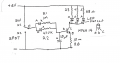
If you use a single pole- doubte throw switch, P-ESP 101, form C, ON-ON, a reasonably simple UP- DN flasher can be constructed. Timing is about 5 sec up, 5 sec down. In UP, current drain about 57 mA when LED are on, DN, LED off drain about 1 uA, almost unlimited battery life when off. If MPSA14 not available , then 2 2n3904 can be connected as a darlington pair & do the same thing. Have you learned the rUp-Dn Flasher 00000.png esistor color code yet?
 
Last edited:

Thread Starter

Vlk

Joined Apr 17, 2015
26
If you use a single pole- doubte throw switch, P-ESP 101, form C, ON-ON, a reasonably simple UP- DN flasher can be constructed. Timing is about 5 sec up, 5 sec down. In UP, current drain about 57 mA when LED are on, DN, LED off drain about 1 uA, almost unlimited battery life when off. If MPSA14 not available , then 2 2n3906 can be connected as a darlington pair & do the same thing. Have you learned the rView attachment 84276 esistor color code yet?
Thank you for your reply! This sounds really good! I haven't learned the resistor color code yet.. But I can see there are tutorials like this. I tried to understand your circuit plan, but I failed.. Am I correct that you have 2 condensators there?
 

djsfantasi

Joined Apr 11, 2010
9,237
So the one I bought or the other one linked? :) I guess I need a switch that stays in position right?
And concerning what you wrote above, I have 3x LED 5mm blue; 40?; 2300 mcd; 3,3 V; 20 mA (which I will need to connect in parallel mode according to wayneh) so I guess the VF is 3,3 VDC, current is 20 mA and VS is 6 VDC. But I am quite unsure what does your three example calculations tell me?
R=5,505 if I counted correctly? Damn, I wish I could understand this more, I must sound like an idiot.. :-D I might just try and buy the parts I linked and see if they work or not. Might be the only way to do this, since I just can't figure out the right numbers and parts...
But I really appreciate your help, thank you for trying to guide me to the right path! I am just so thick-skulled when it comes to physics and mathematics, I apologize for that...
Your assumption about the switch is fine.

The three equations are the solution of the example problem. Each one is one step closer to the solution. We start with

R=V/I

Where V =(6.0-3.3)=2.7VDC and I=0.02

R=2.7/0.02

Not sure how you got 5,505 ohms. The above equation solves to 135 ohms.

Did this help more? Bernard's solution looks interesting. You have some exceptional suggestions from the guys!
 

Thread Starter

Vlk

Joined Apr 17, 2015
26
I really appreciate your help guys, thank you very much for trying to guide me! I am still lost, but's it's definitely not your fault, it's just me and my poor knowledge of physics and electric circuits. I think I am going to experiment somehow and see if I can get this working and done. Might just buy a couple of parts and try and put them together and give it some time to find out how to do it. :)
 

Søren

Joined Sep 2, 2006
472

Thread Starter

Vlk

Joined Apr 17, 2015
26
If the switch is supposed to be controlled by opening the lid of the box, I'd go with a microswitch with a long arm - like this

The arm can be bend to suit the purpose at hand.
It won't fade out until the lid is closed though.
That is actually quite interesting solution! :) I really like what you suggested. And it would make much more sense for my purpose! I wonder how does this work? Would it also work with the fade in/fade out circuit we discussed in this thread?
I imagine that the arm is attached to the lid, so when the arm is pressing the button when the box is closed, the lights are out, and when the arm is lifted and the button released, the lights go on, is that correct?
 

Søren

Joined Sep 2, 2006
472
That is actually quite interesting solution! :) I really like what you suggested. And it would make much more sense for my purpose! I wonder how does this work? Would it also work with the fade in/fade out circuit we discussed in this thread?
I imagine that the arm is attached to the lid, so when the arm is pressing the button when the box is closed, the lights are out, and when the arm is lifted and the button released, the lights go on, is that correct?
That is correct. they're changeover switches, so whether you need it open or closed with the lid open, it's just selecting the right terminal, and it will work in the fader of course - any contact will, even two bare wires touching together would work (but would have a very low WAF, or rather GFAF here).

If you only needed the fade in, you could even have the switch connect your battery, then it would have zero standby current.
You could make a (heart shaped?) window in the lid, if you want the fade out visible with a lid-switch,

Althought as I can see, this switch is made for higher voltage - 125-250VAC - might that be a problem in my only 6 V current?
I found one which is 30V and might be suitable for my cause?http://www.gmelectronic.com/microswitch-zippy-df-p1s-01a-z-p630-342
The voltage on a switch or eg. a capacitor for that matter, tells you the max. limit of the component.
A 250VAC switch can switch 6VDC, while a low voltage switch can't handle a higher voltages than what it's made for.

(And with all rules there are exceptions - you wouldn't want a 250VAC switch for very low currents like µA or nA - there you need gold plated switches which OTOH wouldn't handle inductive high voltage currents. You can totally skip this paragraph though - just building my asbestos, so that certain people won't have to waste their time trying to correct me - although fun for a while, it gets old really fast when lesser people try to correct close to half a century of electronics experience ;))

You can use the switch you found of course, as long as you keep current under 100mA (and if the arm is long enough for your box).

If you're good at wood-working, you could carve or route a "pocket" for the switch, to make it less visible.

And just to make it harder for you to decide :D you could use a reed switch and a magnet, making the switching mechanism invisible:
http://www.gmelectronic.com/microswitch-zippy-sm-05h-07p0-z-p630-037
This one can handle 500mA and Meder is a well reputed manufacturer.
You can get them cheaper at eBay (naturally), but sometimes shipping takes forever (I recently got a batch of 100 pcs of this particular size from China for next to nothing and it only took like 17..18 days, but sometimes it takes 2 or 3 months [or more]).

If going that route, tell me and I can guide you through reversing the action of the switch and other stuff around those thin and fragile (until properly seated with eg. hot glue) glass tubes.

Microswitches are everywhere and generally comes in 4 sizes:
The micro-sized as found in a mouse (at least 2..3 pcs, but 5..6 is more common and some have even more). Their reliability isn't impressive, judging from how often I need a new mouse and in my present mouse (a real Franken-mouse) I routed out space for...
The mini-sized which together with...
The regular size can be found in washing machines, dishwashers etc. mostly the regular size is used here though and then there's...
The biggies which is mostly used in industrial settings and such (which also see a lot of special designed types).

I'd choose a regular sized µswitch if possible - they last longer and are usually build better, but you could go with eg.
http://www.gmelectronic.com/microswitch-zippy-sm-05s-06p0-z-p630-153
or
http://www.gmelectronic.com/microswitch-zippy-sm-05h-07p0-z-p630-037
They might be almost twice the price of the one you found, but nothing's too good for the princess of your heart, right? :)

The reed switch solution would make for a very elegant solution, as it can be completely hidden and it has got the longest life time - at least 1 million actuations (more than a billion if using extremely low currents).
 

Thread Starter

Vlk

Joined Apr 17, 2015
26
That is correct. they're changeover switches, so whether you need it open or closed with the lid open, it's just selecting the right terminal, and it will work in the fader of course - any contact will, even two bare wires touching together would work (but would have a very low WAF, or rather GFAF here).

If you only needed the fade in, you could even have the switch connect your battery, then it would have zero standby current.
You could make a (heart shaped?) window in the lid, if you want the fade out visible with a lid-switch,


The voltage on a switch or eg. a capacitor for that matter, tells you the max. limit of the component.
A 250VAC switch can switch 6VDC, while a low voltage switch can't handle a higher voltages than what it's made for.

(And with all rules there are exceptions - you wouldn't want a 250VAC switch for very low currents like µA or nA - there you need gold plated switches which OTOH wouldn't handle inductive high voltage currents. You can totally skip this paragraph though - just building my asbestos, so that certain people won't have to waste their time trying to correct me - although fun for a while, it gets old really fast when lesser people try to correct close to half a century of electronics experience ;))

You can use the switch you found of course, as long as you keep current under 100mA (and if the arm is long enough for your box).

If you're good at wood-working, you could carve or route a "pocket" for the switch, to make it less visible.

And just to make it harder for you to decide :D you could use a reed switch and a magnet, making the switching mechanism invisible:
http://www.gmelectronic.com/microswitch-zippy-sm-05h-07p0-z-p630-037
This one can handle 500mA and Meder is a well reputed manufacturer.
You can get them cheaper at eBay (naturally), but sometimes shipping takes forever (I recently got a batch of 100 pcs of this particular size from China for next to nothing and it only took like 17..18 days, but sometimes it takes 2 or 3 months [or more]).

If going that route, tell me and I can guide you through reversing the action of the switch and other stuff around those thin and fragile (until properly seated with eg. hot glue) glass tubes.

Microswitches are everywhere and generally comes in 4 sizes:
The micro-sized as found in a mouse (at least 2..3 pcs, but 5..6 is more common and some have even more). Their reliability isn't impressive, judging from how often I need a new mouse and in my present mouse (a real Franken-mouse) I routed out space for...
The mini-sized which together with...
The regular size can be found in washing machines, dishwashers etc. mostly the regular size is used here though and then there's...
The biggies which is mostly used in industrial settings and such (which also see a lot of special designed types).

I'd choose a regular sized µswitch if possible - they last longer and are usually build better, but you could go with eg.
http://www.gmelectronic.com/microswitch-zippy-sm-05s-06p0-z-p630-153
or
http://www.gmelectronic.com/microswitch-zippy-sm-05h-07p0-z-p630-037
They might be almost twice the price of the one you found, but nothing's too good for the princess of your heart, right? :)

The reed switch solution would make for a very elegant solution, as it can be completely hidden and it has got the longest life time - at least 1 million actuations (more than a billion if using extremely low currents).
Thank you very much for your reply! The switch you suggested really changed the whole concept of what I thought I will do and I love it!
The the magnetic switch is even better! I can imagine it must be more difficult to handle, but I love a challenge. :) And you are right, what I wouldn't do for the princess of my heart :-D I am already learning things I would never imagine to learn ever in my life. Things I even quite disliked back in school (physics) :)

I already improved myself and learned about the resistors and also a little bit about capacitors. The only thing which is not clear is how a transistor works, how do I use it and to be more specific, which one to use. I already know how to calculate resistors, but I have no idea how to calculate a transistor. I understand that I need a transistor in order to transform a lower current into a higher one, powering those 3 LEDs connected in parallel, am I correct? As you told me that the voltage rating is more about how much the part can handle and not to which kind of current it is assigned to, I am guessing that it is the same with transistor? Maybe the only thing I need to choose correctly and specificaly here are the resistors at this point?

If you please could give me any guidance, I would really appreciate it so much! And especially with the reed switch solution. I found the local shop have lower voltage ones too, but they are much more expensive: http://www.gmelectronic.com/reed-magnetic-sensor-ka-80-p634-530 However, they have all kinds and they are all in stock, so I can get them quite easily.
 

wayneh

Joined Sep 9, 2010
18,131
The reed switch solution would make for a very elegant solution, as it can be completely hidden and it has got the longest life time - at least 1 million actuations (more than a billion if using extremely low currents).
For what it's worth, this is how a Macbook detects the open/closed state of its screen. There is a small magnet next to the screen that activates a switch next to the keyboard when the screen is closed. I happen to know this because the reed switch chip on my daughter's old Macbook appears to have failed.
 

takao21203

Joined Apr 28, 2012
3,702
That is actually quite interesting solution! :) I really like what you suggested. And it would make much more sense for my purpose! I wonder how does this work? Would it also work with the fade in/fade out circuit we discussed in this thread?
I imagine that the arm is attached to the lid, so when the arm is pressing the button when the box is closed, the lights are out, and when the arm is lifted and the button released, the lights go on, is that correct?
neodymium magnet + suitable inductor
 

Bernard

Joined Aug 7, 2008
5,784
If using reed switch, you still need a form C, single pole- double throw, SP-DT, harder to find & more expensive. The SNAPPY still might be the easiest to use, attach to the inside, back edge side of the box.
How are you mounting the LEDs? Inside of the box with a transparent cover or thru the lid?
Thr transistor is a curren controller, add a little base current & more emitter to colloctor current flows. If MPSA13, MPSA14, not available two 2N3904' s next choice, then two, PN2222A's ,TO92 case. There are several variations & case styles. be carefull.
A small solderable ckt. board would help in mounting parts. Is there a false bottom in box?
 
Last edited:

Søren

Joined Sep 2, 2006
472
If using reed switch, you still need a form C, single pole- double throw, SP-DT, harder to find & more expensive.
No, all that's needed is a regular inexpensive n.o. reed switch!

There's two ways to shave that particular goat - either it's made so the back of the lid holds the magnet, which means that the box is fully open when the circuit starts, or the reed can be "reverse biased" with a small magnet, to bwcome a n.c. reed, which can then have the magnet in the side or front of the lid.

Anyone wanting to throw money away on a SPDT reed can do so in a blink of an eye on eBay, but it's much cheaper to just use two regular reeds and bias one of them :)
However, this is not needed for the circuit at hand.
 

Søren

Joined Sep 2, 2006
472
For what it's worth, this is how a Macbook detects the open/closed state of its screen. There is a small magnet next to the screen that activates a switch next to the keyboard when the screen is closed. I happen to know this because the reed switch chip on my daughter's old Macbook appears to have failed.
I wouldn't be surprised if PC laptops in general worked that way too. Most (all?) can be set to shut down/sleep/hibernate/hybrid hibernate on both the power button and on lid closing - mine is set up to hibernate on both events - although it can't be set to boot on lid open, like at least some Macs do.

It should be easy (apart from dis- and reassembly) to fix this for a gifted guy like you - and think of the points you earn :)
 

wayneh

Joined Sep 9, 2010
18,131
Haha, yes, I think it will not be too hard. Getting to the point of the diagnosis was the hard part. And I found her a utility that intercepts and ignores that switch. This has given a temporary fix until we can tear into the hardware again.
 
Top





