Can I make a breadboared circuit permanent without soldering it on a perfboard?

Thread Starter

whitehaired novice

Joined Jul 15, 2017
289
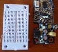
Even as a kid I had poor small muscle control but I was soldering to octal and 9 pin sockets, so it did't matter much. Now, in my old age I have even worse small muscle control--I have to clear up short circuits between two adjacent pins of a perf board almost as often as I don't. The other day I bought a "mystery board" for 50 cents and noticed a white, hard caulk-like substance holding many parts in place. It is NOT used as a heatsink though it might be heatsink compound. It is around two ferrite beads not near each other, a wire wound inductor, five various electrolytics and a couple of small black rectangles. I has, obviously, been squirted one fairly casually, but not wastefully.
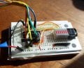
This leads me to think I could just confirm that my breadboard is working and smear glue over everything to make a permanent unit.
I'm going to try it, but if anyone has a suggestion for the type of glue or caulk or ??? I would be glad to know it.
 

crutschow

Joined Mar 14, 2008
38,373
Your "mystery circuit" appears to be a standard PCB with some type of glue to anchor some of the larger components.

The long term reliability of the plug in connections for your breadboard would be of concern.
Those contacts can oxidise and cause unreliable connections.
But if the application is not critical, you could give anchoring the components with some form of glue or conformal coating a try.
Be aware that some silicone rubbers can be corrosive to electrical parts. Make sure it's a non-corrosive type.
 

wayneh

Joined Sep 9, 2010
18,092
I'm going to try it, but if anyone has a suggestion for the type of glue or caulk or ??? I would be glad to know it.
The professional solution is called potting compound. The varieties are vast and overwhelming to meet all sorts of scenarios of cost, required physical properties and so on.

Before resorting to such a thing, though, I'd try to simply 'harden' the breadboard circuit. Shorten all component leads and wires, maybe use cable ties to hold wires together, that sort of thing, maybe some hot glue here and there. Then press a foam down onto the entire thing to help hold everything solidly in place. Make sure there are no mechanical movements transmitted to the board.

If I wanted to use potting, I'd be tempted to try to keep the breadboard separated from all the wires and components so that it might be recovered some day. I don't know how to do that. Maybe you could hold the board upside down and lower it into a tray of the potting compound.
 

WBahn

Joined Mar 31, 2012
32,745
First, keep in mind that this is a pretty expensive route to go. Solderless breadboards are pretty spendy to dedicate them permanently to one circuit. But sometimes ya gotta do what ya gotta do.

Like crutschow, I would be concerned about the long term reliability of the contacts. They will oxidize and then the inevitable slight movements will result in erratic high-resistance contacts. I don't think you will find this to be a good long term solution.

You might consider laying out your components with more separation on your final perfboard or perhaps having custom perfboards made to accommodate greater spacing so that you get fewer bridges.

Another option is to introduce a neighbor kid to the joy of electronics and get them to do your soldering for you. That might turn into a very rewarding relationship for both of you.
 

Wendy

Joined Mar 24, 2008
23,798
After you are sure you have a working schematic, which is what protoboards are about.You can transfer the to something more permanent, Thing is with protoboards all the components are 100% reusable.I have build up a kit of commonly used part that I use for experiments. If you want links to my experiment using protobords I have quite a few, so just ask me and I will give various links. I drew the image shown below

Protoboard 63 columns png.png
A typical protoboard.


...Prototyping Electronic Circuits
 
Last edited:

ebeowulf17

Joined Aug 12, 2014
3,307
Be aware that some silicone rubbers can be corrosive to electrical parts.
Can't emphasize that point enough.

Boy did we have some major headaches because we used a bunch of the wrong kind of silicone in a confined space where its vapors were permanently trapped in a small space with our pcb. Dozens of boards dead within weeks of assembly.

The worst part was that when I finally figured out that the caulk was the problem, none of my coworkers believed me, so we kept making the failing system with the caulk for a few more weeks.

Never again. Learned that lesson the hard way.
 

atferrari

Joined Jan 6, 2004
5,004
Is veroboard an option? I used it for many years now with good results.

Making a protoboard the final suport of your circuit is not only expensive but mechanically unstable if exposed to vibration. Check my suggestion.
 

Thread Starter

whitehaired novice

Joined Jul 15, 2017
289
Is veroboard an option? I used it for many years now with good results.

Making a protoboard the final suport of your circuit is not only expensive but mechanically unstable if exposed to vibration. Check my suggestion.
As to expence, 170 point one are about $1.50 US. 230s come in at about $3 but they are often on sale for $2. Proto boards are only about $1 less. Laying out a bigger board won't work if the components have .1 inch spaced pins--most ICs.
I've built a circuit, tested it and spread it with epoxy. Update tomorrow.
The idea of using foam and a board to clamp them is place sounds good--I never would have thought of it and will try it if the epoxy doesn't work. Thanks all.
 
Last edited by a moderator:

GopherT

Joined Nov 23, 2012
8,009
As to expence, 170 point one are about $1.50 US. 230s come in at about $3 but they are often on sale for $2. Proto boards are only about $1 less. Laying out a bigger board won't work if the components have .1 inch spaced pins--most ICs.
I've built a circuit, tested it and spread it with epoxy. Update tomorrow.
The idea of using foam and a board to clamp them is space sounds good--I never would have thought of it and will try it if the epoxy doesn't work. Thanks all.

Your mystery circuit has many more components that you think - all those SMD resistors add up quickly. Also, the chips are not all available in PDIP (0.1" pin spacing) - they may have to be mounted on adapter boards. All those resistors will not be so nicely positioned on a protonoard vs a purpose-designed multilayer PCB with vias that allow traces to cross-over each other. Limiting yourself to a protoboard / breadboard is going to get very complicated and messy. In fact, you could google an old and famous project referred to as, "Big Mess o Wires" if you want to see what your project will look like once all the jumpers are installed.

Also, why don't you want to want to do PCB? Some vendors in china are doing 10 boards sized 4x4" for less than $30. Way cheaper and easier than protoboards.


----

Big mess o wires computer. Granted, it is wire wrapping, not solderless breadboard but not much different once all of your parts are placed.

IMG_0132.JPG IMG_0133.JPG IMG_0134.JPG
 
Last edited:

Thread Starter

whitehaired novice

Joined Jul 15, 2017
289
Your mystery circuit has many more components that you think - all those SMD resistors add up quickly. Also, the chips are not all available in PDIP (0.1" pin spacing) - they may have to be mounted on adapter boards. All those resistors will not be so nicely positioned on a protonoard vs a purpose-designed multilayer PCB with vias that allow traces to cross-over each other. Limiting yourself to a protoboard / breadboard is going to get very complicated and messy. In fact, you could google an old and famous project referred to as, "Big Mess o Wires" if you want to see what your project will look like once all the jumpers are installed.

Also, why don't you want to want to do PCB? Some vendors in china are doing 10 boards sized 4x4" for less than $30. Way cheaper and easier than protoboards.

----I guess I did not make myself clear--the "mystery board" has nothing to do with this thread--the caulk I noticed on it gave me the idea of using a breadboard and glue. It is just a visual trigger not something I am trying to use, understand, or duplicate.

(reply text extracted from quote by moderator)
 
Last edited by a moderator:

Thread Starter

whitehaired novice

Joined Jul 15, 2017
289
I think I somehow inserted my last reply in the middle of GopherT's message. Sorry. Here is what I said. The "mystery board" has nothing to do with this thread--it was just a mental trigger making me think of gluing parts to a breadboard. I don't want to make or understand the "mystery board." So, I wired up a circuit, tested it and poured epoxy over it. Tomorrow I'll see if it still works. I'll post something either way. Thanks for the suggestions, especially the one about using a sheet of foam and then a hard top to make a pressure held sandwich--I never would have thought of that and it sounds like it should work
 

shortbus

Joined Sep 30, 2009
10,050
Thanks for the suggestions, especially the one about using a sheet of foam and then a hard top to make a pressure held sandwich--I never would have thought of that and it sounds like it should work
As long as you don't have anything that needs a heatsink. Using foam will trap an hear produced in the circuit, even in IC's.
 

Thread Starter

whitehaired novice

Joined Jul 15, 2017
289
As long as you don't have anything that needs a heatsink. Using foam will trap an hear produced in the circuit, even in IC's.
Here is a photo of my epoxied breadboard (maybe I should say “potted”). It is a logic indicator using a hex inverter and 6 LEDs connected so that a wire from the board can be connected to a series CD4000 or 7400 logic IC to make a LED light if the pin is high. Many such boards have only 4 wires, which is probably enough but since I had a hex inverter and a unit with 10 LEDs I went with 6.

The wires bundled with a blue heat shrink section are for power; the ones bundled with yellow are the 6 testing wires. The black tape over the end of the 10 LED unit covers up the unused LEDs, making it easier to read.

The epoxy protects it quite well—the wires won't slip out accidentally. I wouldn't swing it around by a wire, but it surely will withstand the rigors of being taken in and out of a drawer and connected as a daughter-board to a larger breadboard.

I appreciate the help you have given me, including avoiding silicons. While I doubt I'll ever need a similar circuit which needs a heat sink, if I ever do I'll keep the heat sink mostly out of the epoxy.

As a side note, I ordered an 8 watt soldering iron which, I hope, will be small enough to help me solder 0.1 inch spaced pins. There is no way I'll ever be able to use a SMD.
 

Attachments

ian field

Joined Oct 27, 2012
6,536
Sorry--here are images of the breadboard and of the "mystery circuit."

Thanks for pointing it out.
I've seen adverts for prototyping stripboard that match a push in breadboard - apparently, you can overlay the board on top the breadboard and try components as usual - when the circuit is right, you lift the stripboard off the breadboard and solder the component leads to the copper pads.
 

WBahn

Joined Mar 31, 2012
32,745
As to expence, 170 point one are about $1.50 US. 230s come in at about $3 but they are often on sale for $2.
You are certainly getting a much better deal than I ever got. Although I haven't bought a solderless breadboard for a very long time (probably two decades). Most of mine were, admittedly, purchased at Radio Shack (and were of excellent quality -- never had a single problem with any of the couple dozen that I collected over the years), but were correspondingly expensive.

The small ones (~400 connections) were about $7 back then. But looking at Digi-Key I see that many smaller ones are now available at prices that might make this approach reasonable for one-off circuits.

I'm still concerned about oxidation. Also, if your epoxy expands as it cures, it could open up terminal contacts and then coat the pins and insulate them. This is something that you might not see for the first twenty times you did it and then have a problem on the twenty-first board. I don't know if some epoxies will react chemically with some of your components and/or pins and wires or not. Then there's the question of differential thermal expansion as parts of your circuit heat, as well as the impact on heat dissipation to begin with.

I think it's a pretty high-risk endeavor, but if your experiments indicate that it works well enough for you and if you don't use it on projects where the consequences of failure are unacceptable, then it might be satisfactory for you.
 
Top