Need to make circuit flashing 3mm LED after 1 or 2 sec.

Thread Starter

gardenair

Joined Apr 21, 2021
7
Hi,
I am interested to make a very simple circuit. I have DC voltage from 10V to 15V in my home in which i want to add this circuit on it .I want that a 3mm (Red led) may blink after every 1 or 2 sec when it is connected with the circuit.Definitely there will be need of capacitor and resistor etc etc. If any one knows how make to make this circuit with diagram I shall be thankful to him. Currently i am using breadboard for testing and 9 volt batter i am using with it .
Thanks in advance.
 

boostbuck

Joined Oct 5, 2017
1,042
So, you want a LED to flash when it is connected to your ~12V supply?

The simplest solution is to use an LED with an integrated flasher. Then all you need to do is connect it to the supply.

Alternatively a 555 chip and a few components will flash an ordinary red LED. Or even a discrete relaxation oscillator.
 

panic mode

Joined Oct 10, 2011
4,966
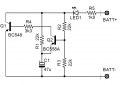
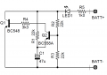
slight tweak to boostbuck circuit in #4:
added C2 so that LED does not light up immediately (you wanted 1-2sec delay).
added R6 to make LED go fully off (optional).
1777990894403.png
 

panic mode

Joined Oct 10, 2011
4,966
one low component count option is to use Schmidt trigger NAND gate. then one input can be used to make an oscillator (input to output resistor, input to GND capacitor). the other input can be used to make delay input to Vcc resistor, input to GND capacitor). and bonus is one still gets three more gates for whatever purpose. of not used, connect their inputs to gnd. load (LED and resistor) from output to Vcc.
if the space is concern there are single gate ICs in SMD though they are only good for up to 5 or 6V meaning there would be need to use voltage regulator or zener...
 

Thread Starter

gardenair

Joined Apr 21, 2021
7
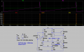
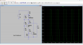
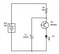
Thanks all for your valuable support .Really appreciate it .Well currently i am a beginner and want to start from small/baby projects.MrChips you have draw a very simple circuit. will try it . I shall try it on LTspice first then do on my breadboard
 

WBahn

Joined Mar 31, 2012
32,789
Thanks all for your valuable support .Really appreciate it .Well currently i am a beginner and want to start from small/baby projects.MrChips you have draw a very simple circuit. will try it . I shall try it on LTspice first then do on my breadboard
Don't be surprised if your simulation doesn't work. That circuit relies on exceeding the reverse breakdown voltage of the collector-emitter junction and many simulation models don't model it.
 

Thread Starter

gardenair

Joined Apr 21, 2021
7
Thanks once again for guiding me.What about proteus software for testing purpose .
Well I shall try it on my breadboard
 

WBahn

Joined Mar 31, 2012
32,789
Thanks once again for guiding me.What about proteus software for testing purpose .
Well I shall try it on my breadboard
It's not the software, but the device model.

If you find a model for the transistor that accurately models the collector-base breakdown and reverse active regions, then the simulation can yield good results. But these are regions that very few circuits operate in and manufacturers don't spend much time modelling them, instead they often use unrealistic parameters for these characteristics.

Also, the behavior of the transistor with an open base is much more complex than the SPICE models are designed for and so models that are intended to apply to this case are actually subcircuits that are crafted to have the desired behavior.

This is actually something that is pretty common in high-fidelity device models. The MOSFET model for the IBM 130 nm CMOS process was actually a subcircuit with over three hundred components. I know because I looked at it naively thinking that I could tweak it to fit our operating regime -- a notion I gave up the moment I opened the file.
 

MrAl

Joined Jun 17, 2014
13,700
Hi,
I am interested to make a very simple circuit. I have DC voltage from 10V to 15V in my home in which i want to add this circuit on it .I want that a 3mm (Red led) may blink after every 1 or 2 sec when it is connected with the circuit.Definitely there will be need of capacitor and resistor etc etc. If any one knows how make to make this circuit with diagram I shall be thankful to him. Currently i am using breadboard for testing and 9 volt batter i am using with it .
Thanks in advance.

Hi there,

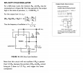
Since you mentioned the 555 timer and other versions were given already, here is a version of a 50 percent duty cycle oscillator using the 555 timer. Not much to it if you want to use this device. Be sure to read the text.
In the formulas, a space is treated as a multiplication. If that's not clear I'll add some dots to show multiplications.

I include a little historical data (ha ha) because I got the original drawing (right side of image) from the back of the package that the 555 timer from Radio Shack came in back in the early 1970's I think it was. They often put a little data on the back of the carded parts they sold that they hung on hooks in the stores.

The clearer drawing I redid so it can be viewed easier. The original text on the card was not that good and the camera I used long ago did not have very high resolution. I don't think I have the actual card package anymore either.
 

Attachments

schmitt trigger

Joined Jul 12, 2010
2,074

ci139

Joined Jul 11, 2016
1,982
if you play/tinker around with the Joule Thief self-feedback and bias capacitors you can achive a different flashing modes - if you got a common mode input choke for/from some (blown) mains AC-DC adapter it will bare you from winding one (an auto TF for the blocking oscillator)
 

MrAl

Joined Jun 17, 2014
13,700
You can just buy a 1 Hz flashing LED 3mm Red for a few cents, Here is one such example.
A simple Google of "3mm blinking led" will bring up a few dozen examples.

Ron
Hi Ron,

I got a few of the 'flickering' LEDs that look like candles. Now they actually make candles with those LEDs inside so they look like candles. They have a lot of different sizes from very small 1 inch diameter 1 inch high to 3 inch diameter and 6 inches high. It got quite a few of them. I also got the non flickering types. I highly recommend them for power outages as they run for several days and you can place them on the floor so you can see where you are walking. Some of the non flickering ones die down faster though sometimes just 24 hours, but they take regular coin cell batteries too so easy to change.
 
Top