Can anyone help me fix this circuit board please?

Thread Starter

DanielHowden

Joined Nov 8, 2019
65
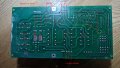
I've been thinking about the latest test Les asked me to perform and I will do this later today. I was just wondering if the fuses had any links to the power supply to the transformer and they do. I have marked this in red highlighter on this well used picture.

I'm not sure if it is significant but I thought I should put it up here.
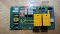
PXL_20231109_193820962.MP1.jpg
 

LesJones

Joined Jan 8, 2017
4,509
The only link between the transformer and the three phase supply is via the circuit board. Bear in mind that if you leave the wire berween the transformer and the board and connect and 240 volt mains to the N and 220 volt connections there will be about 400 volts on the plug end of the lead. I suggest disconnecting this lead from the transformer. It looks like it is connected with push on tags. The 100 watt lamp will probably glow but shoud not be a full brightness. you will probably need to connect the 4 cables from the display to the board. but don't connect any of the other cables to it. The lamp is to limit the current to the display in case it is this that put too much load on the secondary windings of the transformer. Check the voltage at the transformer between the N and 220 volt terminals to make sure the lamp is not dropping the voltage too much for it to work.
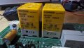
Also can you take a picture of the board from the right hand end looking down at it from an angle of about 45 Deg. so we can see the component to the right of the relay abd raed any markings on the side of the relay. (This may show the coil voltage of the relays.)
You will see from the partial schematic I posted in post #29 that 2 phases of the mains input connect to the bottom end of the fuses and the output side of the fuses passes through the filter components and then to the transformer primary. the last set of tests I requested to the top ends of the fuse holders were to check that there was no shorts in the fiter components.

Les.
 

Thread Starter

DanielHowden

Joined Nov 8, 2019
65
OK, so I just read your post #43. I will redo my test tomorrow and do it fully to your request. I can now see I have connected up the lamp incorrectly so thats another thing I will put right tomorrow. Good news it that the top display did receive power through the transformer. So, when I redo this test for you tomorrow, I will take the circuit board with me and plug in the display connectors only.

https://photos.app.goo.gl/FHpdaBKUinPGXMti9

I think you want a picture of the gold part, I took pictures from various angles so you can get the text on it. It has 1000uf on it so I guess that makes it a capacitor. If I have the picture wrong for you just let me know and Ill take some more.

Link to all the pictures here:-

https://photos.app.goo.gl/s1vAqhvBkeKgJgfGA
 

LesJones

Joined Jan 8, 2017
4,509
I am surprised that the transformer gave any outpyt with a LED lamp connected is series with it. A 100 watt filament lamp will take about 400 mA but I' guessing that your LED lamp is no more than 10 watts (Abour 40 mA) The characteristics of a LED lamp are totally different. You say that you connected the lamp incorrectly but you do not say how you connected it.
As the disply worked without blowing the 2 amp fuse in the plug it seems as though the transformer and the display part is OK. I dont't think you need to repeat that test.
The pictures showed the capacitor OK but it also showed a bridge rectifier. I am guessing that it supplies the power to drive the relay coils. I think the display unit sends low level signals to the two transistors on the board and they in turn drive the relay coils. I think the bridge rectifier and capacitor provide the power to drive the relay coils.
I hoped the pictures would also show some print on the side of the relay showing the coil voltage and possibly the contact layout. In the second picture it looks like there may be some information on the right hand end in that picture. (The top end in the original board pictures.) Could yoy post a picture of that end of the relay ? One thing I would like to be able to prove is that there is no fault that would allow both relays to be energised at the same time. (Which would short out two phases.) When the fault occurred did it blow any fuses or trip breakers in the distribution panel ?

Les.
 

LesJones

Joined Jan 8, 2017
4,509
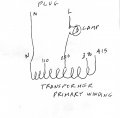
Both of your drawings in post #45 video are electricaly the same. I don't see how the test could have worked at all connected like that as you only has one wire connected. You need both live and neutral connected for things to work.
This is how it should have been connected. (It would not matter if L & N were reversed at the plug.
lamp 001.jpgCan you measure the resistance between the pairs of pins on the relays with the NO contact symbols drawn between them. (This is to check for possible shorted contacts) These are pins 13 & 14 and 23 & 24 on connection diagram 105..220 in the attached datasheet on the relays.

mirrored_03.jpg
I have found some 22 ohm 3W resistors on ebay. eBay item number:262499468756
We have only guessed that they look like 3 watt resistors so can you measure the length and diameter of the resistors so we can compare them to datasheets. When you come to replace the resistors can you confirm that there is no track on the component side of the board that connects to the top end of the resisters.

Les.
 

Attachments

Thread Starter

DanielHowden

Joined Nov 8, 2019
65
OK, so I just did the check you asked for the relays and there is no continuity between the pairs of pins you have pointed out for me to test.

The resistors I purchased have arrived today and they are smaller than the ones on the board. The ones on the board have a body length of 18mm and a diameter of 6.2 at the largest part. The 3w ones I purchased are 15mm long and 4.7mm diameter. I guess these are no good for this job.
 

LesJones

Joined Jan 8, 2017
4,509
You have confirmed that none of the contact on the relays have welded together. Ehen I was looking at various datasheets on 3 watt resistors there was quite a variation of the physical sizes. The are probably OK if they come from a reputable supplier. During normal running they dissipate much less than 3 watts. It is only when the relay contacts open that they disipate any significant power an that will only for a fraction of a second.
Don't forget when you replace the resistors to check if the top (Common) end of the resistors connects to any track on the component side of the board.
I suggest that when you first try it leave the motor connector unplugged from the board. If it powers up OK without the motor c0nnected yoi can the try it with the motor plugged in. Switch at the isolator switch befor re connectin the motor plug.

Les.
 

Thread Starter

DanielHowden

Joined Nov 8, 2019
65
Thank you Les, I will aim to repair the board tomorrow and see if I still have time to test it on the same day.

I do not want to rush this.
 

Thread Starter

DanielHowden

Joined Nov 8, 2019
65
Hi Les, sadly this didn't work. As I look at the board the right fuse immediately blew. I didn't have the motor plugged in at this stage. Maybe there is a problem with the electricity supply at the site and I should talk to the site manager.

I did go ahead and connect the motor directly to the power and it did run fine, so it is a mystery as to why the 240v side of the interface is failing.

I have a tyre fitting machine, more basic as the only electrical part is an on/off foot switch for the motor but that runs fine.

I have had a lot of fun having you help me try to fix this problem though Les and I really do appreciate the time you have put into this.

Daniel.
 

LesJones

Joined Jan 8, 2017
4,509
It sounds like one of the capacitors or the inductor in the input filter is breaking down when the full foltage is applied. The tests you fae done in the past with your meter only applied a low voltage to those components which showed that none of them had a full short circuit. Another possibility is that there is a short on the transformer to earth. Did the left hand fuse look like it had been damaged at all ?
Can you obtain two old fashioned mains voltage incandescent lamps that are the same wattage. 40, 60, or 100 watts ? Two 35 or 50 Watt halogen bulbs could also be used.
The idea is to connect these in place of the fuses so that we can see what is happening without blowing fuses.
If you have an insulation tester you could check for a short between the transformer primary winding and earth using the 500 volt range. If it also had a 250 volt range you could do a better test of the capacitor than was done with your meter.

Les.
 

Thread Starter

DanielHowden

Joined Nov 8, 2019
65
So the left hand fuse was just fine, I left the power on for a little while to give it a chance too.

OK, I have been through our stock of bulbs and we have no incandescent bulbs but I found these 60w bulbs on Amazon if they are good for the test I will get them. I know they are red but I didn't think that would be an issue.

https://www.amazon.co.uk/gp/product/B009JVTMDC/ref=ewc_pr_img_1?smid=A3P5ROKL5A1OLE&psc=1

I don know I should get a better multi meter, I wanted to get an auto sensing one and saw this. What do you think?

https://www.amazon.co.uk/gp/product/B0967M4J1C/ref=ewc_pr_img_2?smid=A3MTD99VI1Y0N8&psc=1
 

LesJones

Joined Jan 8, 2017
4,509
Those lamps will be fine for testing. I thought you may have kept some when replaced lamps at home with CFL or LED lamps. I don't think you need to buy a more expensive meter. The meter in your link will still only test resistance using a low voltage. Being able to measure the value of the capacitors would not help as we were only concerned with them being short circuit or electrically leaky. When you first do the test with the lamps connected in place of the fuses leave the connector that goes to the transformer unplugged at first. As you did not understand connecting thing in series I will explain how to connect the lamps in place of the fuses. Each lamp will have two wires (Single conductors.) coming from it. connect one of these to the bottom right hand fuse holder and connect the other to the top right hand fuse holder. Do the same with the other lamp but to the left hand fuse holder. If both lamps light there will be a short on the 47 nF capacitors, the varistor or the winding on the common mode choke. If only one lamps lights the short will be one of the 2.2nF capacitors. If neither lamp lights then all the filter components are OK. In this case switch off at the isolator , plug the connector from the transformer into the board and turn back on at the isolator. I would expect both lamps to light dimly. If there is a significant difference in brightnes of the two lamps there is a short between the primary winding and earth.

Les.
 

Dodgydave

Joined Jun 22, 2012
11,395
So the left hand fuse was just fine, I left the power on for a little while to give it a chance too.

OK, I have been through our stock of bulbs and we have no incandescent bulbs but I found these 60w bulbs on Amazon if they are good for the test I will get them. I know they are red but I didn't think that would be an issue.

https://www.amazon.co.uk/gp/product/B009JVTMDC/ref=ewc_pr_img_1?smid=A3P5ROKL5A1OLE&psc=1

I don know I should get a better multi meter, I wanted to get an auto sensing one and saw this. What do you think?

https://www.amazon.co.uk/gp/product/B0967M4J1C/ref=ewc_pr_img_2?smid=A3MTD99VI1Y0N8&psc=1

Have a look at these multimeters.

https://cpc.farnell.com/w/c/test-eq...selection=auto&st=Multimeter&sort=P_PRICE#top
 

Thread Starter

DanielHowden

Joined Nov 8, 2019
65
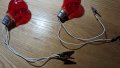
Hi Les, the bulbs didn't come in till late today so I didn't get a chance to test. However, I did get them ready.

I understand that I need to do this test with only the mains power connected to the board and take it from there.

I have a full on day tomorrow so I may not even get to do this test until Tuesday.

Daniel.

PXL_20231119_182537334.jpg
 

LesJones

Joined Jan 8, 2017
4,509
I don't like the idea of using croc clips to connect to the fuse holders as they could move and short together. this risks destroying the board as the current available would melt tracks on the board. I would either solder wires to where the fuse holders are soldered to the board or solder them to the ends of some fuses that had already blown open circuit. Also I would use lamp holders rather than just soldering to the bulbs. You are correct that you should start with just the power plug from the isolator switch connected to the board. neither of the bulbs should light when power is switched on. (Not even dimly.) The next step is to plug in the connector that goes to the transformer primary. (These wires should be connected to the N & 415 volt connections on the transformer. (NOTE the one that connect to N is NOT mains neutral it is one of the phases.)

Les.
 

Thread Starter

DanielHowden

Joined Nov 8, 2019
65
Hi Les, I do read your comments regarding the safety of my bulb setup and I do agree with what you say. Please don't be offended when I tell you that I used the bulbs as I have shown them but I was super careful when attaching them and where I placed the bulbs keeping in mind your comments at all times.

The result of the test was that both bulbs lit dimly. I turned the lights off in my workshop so that it would show on a photo.

So you have said that if the lights lit dimly then there is a short on the 47nF capacitors so it looks like I should go ahead and replace those.

Daniel.

PXL_20231121_160031369.jpg
 
Top