Cable harness tester with 3 connectors (<30 test points)

Thread Starter

sahbi97

Joined Feb 25, 2025
10
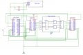
im working on a DIY cable harness tester project (to check continuity, cross-wiring, and resistivity) and could really use some guidance. As a newbie, I’ve hit a wall with both the schematic design and coding, and I’m not sure where to turn next.

What I’m trying to build:

  • A low-cost tester that can verify continuity between wire ends.
  • Detect cross-wiring/shorts between pins.
  • Measure resistance (for basic quality checks).
    I’m unsure how to design the circuit to handle multiple wires and avoid false readings and also struggling to write the code
 

dendad

Joined Feb 20, 2016
4,636
You could use a couple of these...
https://www.ti.com/lit/ds/symlink/cd74hc4067.pdf?ts=1742820897918
and boards are available on Ebay for just a couple of dollars each.
1742900496375.png
Have a couple going from say 5V fed via a resistor to each wire, than the other end, another couple feeding to a 1K termination resistor to gnd, the signal going to an Arduino analog input.
Select the sender wire to feed one at a time and then read each receiver to see if the only the wire you want reads 2.5V.
1742901415017.png
An series LED could be added to each wire because, as everyone knows, blinkin lights make things work better.
 
Last edited:

Thread Starter

sahbi97

Joined Feb 25, 2025
10
list of materlias that i have bought : power supply 5v/3a , AMS1117 , esp32 wroom , 2 muxs 16 channels and LCD16*2
And I picked Esp32 cuz I'm gonna share the result not only through LCD but also on a dashboard (IoT) so I need a microship who has wi-fi integrated in it

Can you check this schematic for me?

PS: I’m still a beginner in embedded systems, I mostly follow tutorials and experiment with small modifications.
 

Attachments

dendad

Joined Feb 20, 2016
4,636
Ah, I see you posted a circuit while I was drawing one and editing my post.
A couple of things,
The 4067 chips you have drawn with 25 pins but should be 24.
I usually have a 100nF cap at each IC, as close as you can.
You have the LCD SDA and SCL pins joined together. They need to go to the appropriate pins on the ESP32.
SDA goes to 21 and SCL to 22.
Get the LCD running first. Make sure it is a 3V3 version, or use a 3V3 OLED display.
Have a look at https://randomnerdtutorials.com for a lot of help.
For example... https://randomnerdtutorials.com/esp32-i2c-communication-arduino-ide/
And look at how I send a signal and read the analog value to "measure" the resistance. Use 3V3 instead of 5V.
 

Thread Starter

sahbi97

Joined Feb 25, 2025
10
I really appreciate your support, and I'll do my best. I'm grateful for your help and hope you’ll assist me with any other questions I might have in the future.
 

MisterBill2

Joined Jan 23, 2018
27,323
Is this to be an automated tester?? Or will a totally manual tester be adequate?? How many connector types need to be tested??
I was responsible for body wire harness testers at a major auto company for a while. Those tests were mostly automated, programmed and fault reporting on a digital display, lots of connections to the different harness breakouts.
 

Thread Starter

sahbi97

Joined Feb 25, 2025
10
yes its an automated tester ,im working on small cables either they have 2 , 3 or 4 connectors
heres an example im working on :
- main connector ( Connector A) has 4 pins goes to Connector B and C each one has 2 pins (mapping )
 

MisterBill2

Joined Jan 23, 2018
27,323
OK, a simple fast tester will supply a different voltage to each pin on connector "A", and use an analog input to verify the correct voltage on each pin of the other connectors. That test can be run with either a PLC with an analog input module, or a PC with an analog input board. The voltage to supply can be from a low power regulated DC supply feeding a chain of resistors to provide all of the different voltages. Since almost no current is drawn, the voltages will be stable enough. and the PLC can also provide the controls for the mechanical portion of the automation. The total test time should not need to be more than five seconds.
I have done similar testers several years ago.
 

Thread Starter

sahbi97

Joined Feb 25, 2025
10
OK, a simple fast tester will supply a different voltage to each pin on connector "A", and use an analog input to verify the correct voltage on each pin of the other connectors. That test can be run with either a PLC with an analog input module, or a PC with an analog input board. The voltage to supply can be from a low power regulated DC supply feeding a chain of resistors to provide all of the different voltages. Since almost no current is drawn, the voltages will be stable enough. and the PLC can also provide the controls for the mechanical portion of the automation. The total test time should not need to be more than five seconds.
I have done similar testers several years ago.
Can you please share the schematic with me? It would be really helpful.
 

Thread Starter

sahbi97

Joined Feb 25, 2025
10
If you're looking for a cable harness tester with 3 connectors and less than 30 test points, here are a few things to consider:

1. Features to Look For:

✅ Continuity Testing – Ensures all wires are correctly connected.
✅ Short Circuit Detection – Identifies unintended connections.
✅ Open Circuit Detection – Detects missing connections.
✅ Resistance Measurement – Optional but useful for verifying proper connections.
✅ Customizable Test Sequences – If you need repeatability.

2. Potential Solutions:

  1. Prebuilt Cable Testers
    • BK Precision 878B – Basic wire tester with up to 64 test points.
    • Cirris EasyWire CR – Modular system for custom harnesses.
    • E-Z-Hook XKM Series – Small harness testers with 20-30 points.
  2. DIY / Arduino-Based Solutions
    • If cost is a concern, you can build one using Arduino Mega + Multiplexers (74HC4051) with a simple continuity and short-circuit detection algorithm.
    • Raspberry Pi GPIO-based testers are also an option.
3. How to Choose?

  • If it’s for production testing → Go for a commercial unit with automation.
  • If it’s for prototyping/debugging → A DIY solution with an Arduino or Raspberry Pi could work.

Would you like a recommendation for a specific brand or a DIY circuit design?

I'm currently doing an internship where they suggested I work on a cable tester, so I'm looking for a DIY design, which would be really helpful.
 

MisterBill2

Joined Jan 23, 2018
27,323
I am not able currently to create a suitable schematic drawing. For the "A" connector, which gets the voltage supply, a simple 24 volt DC supply will be the simple choice, with a string of 31 resistors in series between positive and negative outputs. Then starting at the +24 volt side, each pin of connector "A" will connect to a different resistor junction, with the last pin tied to the top of the last resistor in the string. This scheme will provide a sufficient voltage difference to work reliably with even an 8-bit A/D input converter.
Note that the DC supply negative side must also connect to the analog input system DC common side.
For the "B" and "C" connectors, each pin must connect to a different analog input. This will probably demand using two 16 channel analog input modules..
Since I have no idea as to what analog input modules the TS will use, that connection portion is not able to be presented.
Note that the same scheme can also be used with a group of four arduino modules, although the programming will probably be a bit different. That will also be the very least expensive scheme for a fast test of all the harness conditions, except for conductor resistance.
 

MisterBill2

Joined Jan 23, 2018
27,323
Measuring resistance was an option, but is not normally a test done in production testing. The scheme described in posts #14 and #16 will catch mis-wires, opens, and shorted circuits at as fast a speed as the processor s can read voltage and execute a bit of logic. Checking each wire for a voltage drop at some current requires a quite different arrangement.

So at this point we need a comment from the initial poster as to exactly what is needed.
 

MisterBill2

Joined Jan 23, 2018
27,323
IF that circuit only provides voltage to one wire at a time, and only checks for a voltage on one wire at a time, it will be unable to sense that two wires have been connected together. In addition, it will be much slower and much more complex because of needing to select two connections for each test.
 
Top