Facebook
 Google
 GitHub
 Linkedin
Edit: to any newcomer to this thread, I still haven't solved my issue but the thread has helped my formulate it better. So I recommend reading post #13 as I feel it really gets to the heart of my misunderstanding.
Hi everyone,
I am working on an off grid solar setup and I just realised that for a constant amount of amps, the higher the voltage, the smaller the cable gauge can be.
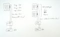
In my instance I am using solar panels with a maximum current output of about 15A and voltage of about 30V.
The Victron toolkit calculator tells me that for a single panel, a 10mm2 cable run of 10m (20m two ways), will drop a dangerous amount of voltage but with 4 panels in series, hence 120V I can go all the way down to 4mm2 while my current remains at 15A.
My experience of electricity is through electronic circuits so this is really surprising to me because resistors are rated for power, so increasing voltage for a constant amount of amps will eventually cause the resistor to release the magic smoke, which is the exact opposite behaviour.
I was expecting cable ratings to follow the same rule, considering a cable as being a very long and low value resistor.
Can someone please explain to me why I was wrong?
Hi everyone,
I am working on an off grid solar setup and I just realised that for a constant amount of amps, the higher the voltage, the smaller the cable gauge can be.
In my instance I am using solar panels with a maximum current output of about 15A and voltage of about 30V.
The Victron toolkit calculator tells me that for a single panel, a 10mm2 cable run of 10m (20m two ways), will drop a dangerous amount of voltage but with 4 panels in series, hence 120V I can go all the way down to 4mm2 while my current remains at 15A.
My experience of electricity is through electronic circuits so this is really surprising to me because resistors are rated for power, so increasing voltage for a constant amount of amps will eventually cause the resistor to release the magic smoke, which is the exact opposite behaviour.
I was expecting cable ratings to follow the same rule, considering a cable as being a very long and low value resistor.
Can someone please explain to me why I was wrong?
Last edited:


")