Buck Converter output not reaching reference voltages above 13V

crutschow

Joined Mar 14, 2008
38,598
I'm confused. If the system is unstable, shouldn't it be unstable no matter what reference voltage I use?
If the system was perfectly linear, yes.
But a real circuit is never totally linear, thus changes in the operating point can have a small effect on the loop dynamics.
So if the loop is close to instability, it can cause the circuit to become unstable as you change the set-point voltage.

You should do a loop stability analysis.
You can simulate this if you substitute a linear gain block in the feedback loop for the PWM modulator.
You just need to calculate the gain value for the modulator, i.e. what is the change in the average output voltage from the M1 PWM transistor output divided by the change in the modulator input voltage (the plus input of the U3 LM339).
 

Thread Starter

zemus_1

Joined Apr 4, 2018
20
If the system was perfectly linear, yes.
But a real circuit is never totally linear, thus changes in the operating point can have a small effect on the loop dynamics.
So if the loop is close to instability, it can cause the circuit to become unstable as you change the set-point voltage.

You should do a loop stability analysis.
You can simulate this if you substitute a linear gain block in the feedback loop for the PWM modulator.
You just need to calculate the gain value for the modulator, i.e. what is the change in the average output voltage from the M1 PWM transistor output divided by the change in the modulator input voltage (the plus input of the U3 LM339).
I don't see the procedure you're describing. Could you explain it again?

So, I tried to find the transfer functions of
-buck converter: (1+C*Resr*s)*Rload/(Rload+(L+Rload*Resr*C)*s+((Rload+Resr)*L*C*s^2))*Vin
-PI: R5/R6+1/(R6*C2*s);
-and modulator: 1/∆Vtriangle
Using Matlab, analyzed the open loop stability with a bode plot. How does reference voltage come into play in all these?
 

crutschow

Joined Mar 14, 2008
38,598
I don't see the procedure you're describing. Could you explain it again?
You simulate the circuit as shown, except you replace the PWM modulator with a linear gain block, and you do an AC frequency-domain simulation instead of a transient time-domain simulation.
That allows you to generate a Bode plot of the feedback loop and find the stability margin.
How does reference voltage come into play in all these?
It doesn't.
The loop response is an AC response which is not affected by DC voltages.

If you want to design feedback loops than you need to learn about how to do Bode plots and understand the criteria for a stable loop.
Here and here are a couple of references to start.
 

Thread Starter

zemus_1

Joined Apr 4, 2018
20
You simulate the circuit as shown, except you replace the PWM modulator with a linear gain block, and you do an AC frequency-domain simulation instead of a transient time-domain simulation.
That allows you to generate a Bode plot of the feedback loop and find the stability margin.
So, remove U3, U2, U1; connect control output to mosfet gate through a gain block? Gain block made by inverting a inverter? If there is no pwm signal, how will the circuit work? Completely lost here. :confused:
 

Alec_t

Joined Sep 17, 2013
15,132
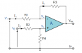
Since R12/R4 form a 2:1 voltage divider and Vin is 20V, the maximum useful reference voltage for the feedback would be 10V.
 

Thread Starter

zemus_1

Joined Apr 4, 2018
20
Since R12/R4 form a 2:1 voltage divider and Vin is 20V, the maximum useful reference voltage for the feedback would be 10V.
Those resistors are part of the differential amplifier to find the error. Since R7=R9=R4=R12, then error=Vout-Vref
Captura de pantalla 2018-04-07 a las 11.40.13.png
Captura de pantalla 2018-04-07 a las 11.40.37.png
 

Alec_t

Joined Sep 17, 2013
15,132
That's why your output is lower than you want. Try with R7 reduced significantly, to give the error amp a gain >1.
 
Last edited:

crutschow

Joined Mar 14, 2008
38,598
So, remove U3, U2, U1; connect control output to mosfet gate through a gain block? Gain block made by inverting a inverter? If there is no pwm signal, how will the circuit work?
You are doing an AC simulation of linearized components.
PWM is part of the transient simulation and is replaced with a gain block for the PWM (which includes the MOSFET).
If you think about it, all the PWM circuit does is covert the error signal to an averaged DC signal at the output. That's what the PWM gain block emulates for AC simulation purposes.

Since we are only interested in circuits that affect the loop response, the simulation circuit will consist of U4 with its components, the PWM gain block (with the PWM modulator gain), and the output LC filter. No MOSFET or anything that does not affect the AC response is needed or included.

The gain block can be simulated using "e", the voltage-dependent-voltage-source in LTspice.
The modulator gain in this design is the maximum output voltage (20V) divided by the peak-to-peak modulator sawtooth voltage.
It the simulation the sawtooth is about 2.8Vpp, so the modulator gain would be Amod = 20V/2.8V = 7.14.
To enter this gain, right-click on the gain-block, "E" in the schematic, right-click the line "Value" and enter 7.14.
Note that the signal polarity of the gain block needs to be the same as the PWM circuit, so that you have negative feedback around the loop.

To insure that U4 is properly biased for the simulation, connect two 1k resistors in series from U4's output to the (-) input with a 1 farad capacitor from the two resistor's junction to ground.
That will allow the op amp to not stay properly biased without affecting its AC loop response
 

Thread Starter

zemus_1

Joined Apr 4, 2018
20
You are doing an AC simulation of linearized components.
The gain block can be simulated using "e", the voltage-dependent-voltage-source in LTspice.
The modulator gain in this design is the maximum output voltage (20V) divided by the peak-to-peak modulator sawtooth voltage.
It the simulation the sawtooth is about 2.8Vpp, so the modulator gain would be Amod = 20V/2.8V = 7.14.
To enter this gain, right-click on the gain-block, "E" in the schematic, right-click the line "Value" and enter 7.14.
Note that the signal polarity of the gain block needs to be the same as the PWM circuit, so that you have negative feedback around the loop.

To insure that U4 is properly biased for the simulation, connect two 1k resistors in series from U4's output to the (-) input with a 1 farad capacitor from the two resistor's junction to ground.
That will allow the op amp to not stay properly biased without affecting its AC loop response
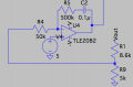
Not sure if this is what you mean.
 

Attachments

crutschow

Joined Mar 14, 2008
38,598
Not sure if this is what you mean.
Close.
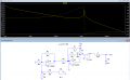
You just need to open the loop and add an AC source for the stimulus (V2 below).
Also, the worst-case stability is with no load so I removed the output resistor load.

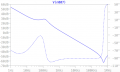
The large peak in the gain and rapid phase-shift change at about 1.3kHz indicates a serious loop instability which can cause and oscillation.
You need to adjust the compensation to reduce that peak with the phase-shift staying well above 180° until the gain goes below 0dB.

Be sure and include the actual values of the inductor resistance and the output capacitor equivalent series resistance (ESR) as that affects the response at that peak.


upload_2018-4-7_15-7-57.png
 

Thread Starter

zemus_1

Joined Apr 4, 2018
20
Close.
You just need to open the loop and add an AC source for the stimulus (V2 below).
Also, the worst-case stability is with no load so I removed the output resistor load.

The large peak in the gain and rapid phase-shift change at about 1.3kHz indicates a serious loop instability which can cause and oscillation.
You need to adjust the compensation to reduce that peak with the phase-shift staying well above 180° until the gain goes below 0dB.
Captura de pantalla 2018-04-07 a las 18.45.44.png
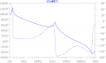
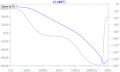
Something like this is stable right? It just need maybe a bit more of phase margin?

Also, is there a way to measure ESR when it doesn't show up on the datasheet?
 
Last edited:

ebp

Joined Feb 8, 2018
2,332
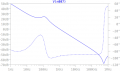
You probably could raise your 0 dB crossover frequency by a factor of at least 5 for faster dynamic performance, but at this point I think you are probably far better off to continue experimenting with the otherwise excellent response shown at #33. Good luck!
 

Thread Starter

zemus_1

Joined Apr 4, 2018
20
That looks very good.
You have over 80° of phase margin.
What circuit configuration and values did you use.
Same circuit. Calculated the gain values for the PI control for a chosen phase margin. It looks good, but I had to increase Cout to 1mF and assuming an ESR of 1ohm or more. I was wondering, since I'm connecting a lead acid battery as load, and how its resistance is low; I can make the loop stable using 10uH and low ERS. However, any load with higher resistance will make it unstable. So, what do you guys think? Should I choose the one that is stable with any load, but cap>=1mH and ESR>=1ohm, or stable for just battery with 10uH cap?
 

Attachments

crutschow

Joined Mar 14, 2008
38,598
So, what do you guys think? Should I choose the one that is stable with any load, but cap>=1mH and ESR>=1ohm, or stable for just battery with 10uH cap?
A lead-acid battery is a very low impedance, so will swamp the effect of the capacitor value and its ESR.
So you will need to make the circuit stable with a value of essentially zero ESR (or what the battery impedance is).
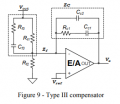
That may require the addition of some lead compensation, such R13C13 in the Type III circuit shown below and described on page 13 of the reference I posted. Type III compensation can be made stable with a low ESR.

upload_2018-4-8_20-50-58.png
 

Thread Starter

zemus_1

Joined Apr 4, 2018
20
I tested the circuit with 80º margin with a resistive load. The duty ratio still changes as the reference goes above 13V. So, I wonder if the stability is still the issue here.

I tried changing the duty ratio manually, and the output does change accordingly and it can reach any voltage.

The lead compensation you mentioned. I just can't see how I can add it to my PI control.
 
Top