Facebook
 Google
 GitHub
 Linkedin
Guys:
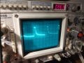
I'm designing a circuit where the supply is 15Vdc. I have chips that run on 5Vdc, so I have added a buck converter (Diodes, Inc. #AP62201). This is on a PCB for embedded work. As far as I can tell, I have hooked it up exactly like in the spec sheet (see schematic), but the output is the wave you see below. It is low-frequency (about 100 Hz) and the peaks are about 5V. I put a 120-ohm resistor at its output to give it some load. The input from my benchtop power is currently only 5V, but I'm afraid to turn it up until I find out about this wave (the MCU is powered by this regulator).
What am I doing wrong? Thanks for any insights.


Don
I'm designing a circuit where the supply is 15Vdc. I have chips that run on 5Vdc, so I have added a buck converter (Diodes, Inc. #AP62201). This is on a PCB for embedded work. As far as I can tell, I have hooked it up exactly like in the spec sheet (see schematic), but the output is the wave you see below. It is low-frequency (about 100 Hz) and the peaks are about 5V. I put a 120-ohm resistor at its output to give it some load. The input from my benchtop power is currently only 5V, but I'm afraid to turn it up until I find out about this wave (the MCU is powered by this regulator).
What am I doing wrong? Thanks for any insights.
Don