Joule Thief Strange Behavior

Thread Starter

vandveuser16776

Joined Feb 21, 2026
121
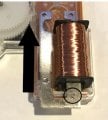
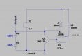
I built a Joule Thief flasher using a 5:1 inductor ratio to see what would happen. I charged a 2200 µF capacitor to 3.7 V and used it as the power source instead of a 0.9 V battery. At first, the LED lit at maximum brightness and stayed on, then gradually dimmed over about 4 seconds. After that, it began flashing at the same brightness for a while. Suddenly, the LED turned on at about half brightness, stayed like that for a second or two, and then stopped working. What makes me wonder is the last second constant on, no matter how short, it tells that the circuit was back to oscillation at full speed again before it run out of power completely. How can I explain this?
 

Attachments

MrChips

Joined Oct 2, 2009
34,626
transistor oscillator.jpg

The operation of that circuit is complex. When the LED is fully lit, you need to distinguish between fast oscillation and constant DC. In order to understand what is happening, you need to examine the signals with an oscilloscope.

Changing the turns ratio might not accomplish what you think. L1 induces a voltage into L2, not the other way around. Hence, a 1:5 ratio means that the base bias is now 5 times higher than when using 1:1 ratio.

LEDs, D1 and D2, are off when Q1 conducts, and that happens when the base of Q1 is high. This happens on turn on.
When Q1 is turned on, reversed induced current drives the base low and Q1 turns off.

The time-constant of R1 x C1 is about 47 ms. What is the flash rate you are observing?
 

MrChips

Joined Oct 2, 2009
34,626
I have tested your circuit on a breadboard with a 1:1 transformer.
As far as I can tell, this is not a Joule Thief circuit. It is an oscillator starting around 100 Hz at Vs = 0.6 V.
The LED is lit with increasing brightness from Vs = 1.6 V at an oscillator frequency of about 500 Hz.

I used only one red high efficiency LED with 1k Ω series resistor.
 

BobTPH

Joined Jun 5, 2013
11,463
As far as I can tell, this is not a Joule Thief circuit. It is an oscillator starting around 100 Hz at Vs = 0.6 V.
It is the standard Joule thief except for the addition of C1 and unusually large R1. I expect that change causes the low oscillation frequency. The Joule thief I built oscillated at about 65 KHz.
 

MrChips

Joined Oct 2, 2009
34,626
It is the standard Joule thief except for the addition of C1 and unusually large R1. I expect that change causes the low oscillation frequency. The Joule thief I built oscillated at about 65 KHz.
You're right. I was confused for a moment because I was thinking of the NPN-PNP code oscillator circuit.

Joule Thief Circuit

Joule Thief.jpg


Joule Thief Flasher
Joule Thief flasher.jpg
 

Thread Starter

vandveuser16776

Joined Feb 21, 2026
121
Thanks @MrChips and @BobTPH. The flasher blinks at about 1 Hz. Each time the LED turns on, there is a burst of high frequency that disappears from the screen before I can read it. Finally, when the LED turns on steadily, the waveform is around 44 kHz. As the LED fades to invisibility (there may still be some light emission, but not visible), the circuit remains at that frequency, producing a nearly perfect sine wave with about 1.4 V peak-to-peak. The inductor was made of the ferrite rod 6mm X 20mm and I found this discarded wall clock, took the bobbin and used the wires to build this inductor. The wire is many times thinner than hair, and it was probably 1000 turns or more (just used cordless drill kept on till all the wire on the bobbin was on the rod!) The result was primary 350Ω and 500mH and secondary 100Ω and 110mH. So, the bottom line is when the 2200μF capacitor is drained to a level that there is no flashing, there is still a some oscillation in the circuit.
PS. the probes were connected to the legs of the LED
 

Attachments

Last edited:
Top