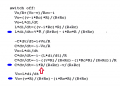
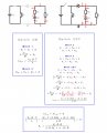
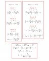
Here is the other method using the first equations, substituting Vc, and the result it's clearly non sense. 1 = 0. Did you see any error in my procedure?
Ok so you are saying it seems hard to solve for either the average inductor current or the average capacitor voltage? Yes, both of them.
I have to ask again though, in your equation:
iL=-Vo/(R*(1-D))
how do you intend to get the numerical value for iL when you dont know Vo yet?
It is true that the average Vo does not change, but we still must know what it is to be able to get iL in that] equation. That's why it is better to try to eliminate it altogether.
I just need the "iL" equation to substitute inside the inductor current increments when we add more parasitic components, just for that. Now look unnecessary because we just took the cap inner resistance as parasitic component, but shows that the procedure fails at some point, which is what i'm trying to figure it out.
The actual average iL will include the variable Rc which is the cap ESR value
That what I expected, but I didn't appear that variable in the Average "iL"
Oh ok i just wanted to make sure i understood the problem you ran into.
I didnt want to just post the equations as i wasnt sure if you wanted to see them yet until you tried again, but i dont think it will hurt and then you can try to reproduce them perhaps using your mesh method.
Here's what i got for the average inductor current:
iLavg=(D*E*(R+Rc))/((D-1)*R*(D*R-R-Rc))
and for the average cap voltage:
vCavg=(D*E*R+Rc*D*E)/((D-1)*R-Rc)
I will check these in the numerical solver also very soon.
[LATER]
Ok they seem to check out ok but i cant go too low on Rc in the program or i get numerical problems. It would probably be better to include another damper component like Rs or RL.
[LATER LATER]
I found i had to go many more cycles before reaching steady state in the program, that was the problem. Results with Rc=0.1 match to about 5 significant digits now.
Here's what i got for the average inductor current:
iLavg=(D*E*(R+Rc))/((D-1)*R*(D*R-R-Rc))
and for the average cap voltage:
vCavg=(D*E*R+Rc*D*E)/((D-1)*R-Rc)
Can I see your node equations from the beginning please? I think the starting point it's my problem. Thank you very much
Here's what i got for the average inductor current:
iLavg=(D*E*(R+Rc))/((D-1)*R*(D*R-R-Rc))
and for the average cap voltage:
vCavg=(D*E*R+Rc*D*E)/((D-1)*R-Rc)
Can I see your node equations from the beginning please? I think the starting point it's my problem. Thank you very much
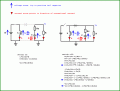
Yes, see the attachment. Note 'i' is inductor current, 'v' is cap voltage (not output voltage).
We got lucky here because we dont have any RL, Rs, or Vd so the output voltage Vo equals the voltage across the inductor. If that was not the case, we'd have to do more work.
One more note, that all the arrows are in the same direction for BOTH circuit modes 'on' or 'off'.
Also, the final equations in the 'off' mode are marked with a blue oval shaped dot.
Also note that we need a third equation for each set, the output equation for Vo which should depend only on the inductor current and cap voltage and the component values and not on any derivatives.
Last but not least, these drawings are basically line drawings so the best file format is the .gif file format. Bmp is too big and jpg is for high color content and complex pictures and usually introduces unwanted distortion into the picture.
Yes, see the attachment. Note 'i' is inductor current, 'v' is cap voltage (not output voltage).
We got lucky here because we dont have any RL, Rs, or Vd so the output voltage Vo equals the voltage across the inductor. If that was not the case, we'd have to do more work.
One more note, that all the arrows are in the same direction for BOTH circuit modes 'on' or 'off'.
Also, the final equations in the 'off' mode are marked with a blue oval shaped dot.
Also note that we need a third equation for each set, the output equation for Vo which should depend only on the inductor current and cap voltage and the component values and not on any derivatives.
Last but not least, these drawings are basically line drawings so the best file format is the .gif file format. Bmp is too big and jpg is for high color content and complex pictures and usually introduces unwanted distortion into the picture.
Also, i had to correct post #27 due to the slight error in numerical calculation.
Also, and i think you may have observed this already, in the full blown circuit with Vd, RL, Rd, Rs, and Rc, the cap and cap ESR form a simple averaging network and that means that any averaged voltage that appears at Vout will also appear across the capacitor because the average of an average is the same average. This gives us a good test point for the solutions in that we must compute averages Vc=Vout or else we made a mistake
Also, with the cap and cap ESR any of these circuits where the average Vout appears at the top of the ESR resistor (as drawn here in various places) the cap will attain the same average voltage as the output, so it's not just this circuit. I dont like to use that as a starting point logistic though, i would rather see that fall out of the analysis first.
Yes, see the attachment. Note 'i' is inductor current, 'v' is cap voltage (not output voltage).
We got lucky here because we dont have any RL, Rs, or Vd so the output voltage Vo equals the voltage across the inductor. If that was not the case, we'd have to do more work.
One more note, that all the arrows are in the same direction for BOTH circuit modes 'on' or 'off'.
Also, the final equations in the 'off' mode are marked with a blue oval shaped dot.
Also note that we need a third equation for each set, the output equation for Vo which should depend only on the inductor current and cap voltage and the component values and not on any derivatives.
Last but not least, these drawings are basically line drawings so the best file format is the .gif file format. Bmp is too big and jpg is for high color content and complex pictures and usually introduces unwanted distortion into the picture.
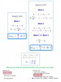
I've tried to understand yours steps at first, and you calculated the equivalency marked in red with the Mesh System I guess.
My question is, it's possible to just use both equation marked in red and calculate Vo (Ouput Voltage) ? (I upload an Image just for in case you can't see it)
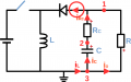
I think I found and error in my schema, I left the current from diode wich is the inductor current, what a fool I am!
I will try to redo the calculations now.
Mr.AI, I have another question related to Buck Boost.
As we set: " iL + (Increment i_L )/ 2 > 0 " in order to calculate the minimum Inductance.
In case of the Capacitance, should be something like : " Vc + (increment Vc)/2 > 0 " for the minimum capacitance?
Is this correct? ( in ideal case of course )
I've tried to understand yours steps at first, and you calculated the equivalency marked in red with the Mesh System I guess.
My question is, it's possible to just use both equation marked in red and calculate Vo (Ouput Voltage) ? (I upload an Image just for in case you can't see it)
Do you mean take the negative of one of those quantities and call it Vo?
I think the term L*di/dt should be held as a different quantity in each set. In other words, i dont think we should take any shortcuts.
The reason why it may not look correct at first glance is because *part* of the equation divided by 'R' leads to a term with Rc in the numerator, but the full equation includes a negative 'i' (-i) term also and when resolving those three resulting terms into just two terms, we have no Rc in the numerator we get the R that way.
Mr.AI, I have another question related to Buck Boost.
As we set: " iL + (Increment i_L )/ 2 > 0 " in order to calculate the minimum Inductance.
In case of the Capacitance, should be something like : " Vc + (increment Vc)/2 > 0 " for the minimum capacitance?
Is this correct? ( in ideal case of course )
You mean min inductance and capacitance for continuous mode operation?
The inductor current should never go to zero and the cap voltage should never go to zero either. If either of these happen, then that means the circuit runs out of energy in order to maintain operation as usual. The only exception is if it goes exactly to zero and then the next cycle begins immediately, so it's really less than zero but using zero is ok because that will tell the absolute min, which if exceeded, will cause at least some dwell time at zero and that becomes discontinuous.
Do you mean take the negative of one of those quantities and call it Vo? I mean, taking this two equations, and calculate the increments.
Then
Each increment represent Rising and Falling current of the inductor, am I wrong?
I think the term L*di/dt should be held as a different quantity in each set. That does it mean, the increments from ON and OFF are different, is that possible?
The reason why it may not look correct at first glance is because *part* of the equation divided by 'R' leads to a term with Rc in the numerator, but the full equation includes a negative 'i' (-i) term also and when resolving those three resulting terms into just two terms, we have no Rc in the numerator we get the R that way.
You mean min inductance and capacitance for continuous mode operation?
The inductor current should never go to zero and the cap voltage should never go to zero either.
Yes, just for the Continuous Mode Sorry.
Another proof that my equations were wrong is that Minimum Capacitance is Zero when Duty Cicle is 50%.

 Facebook
 Google
 GitHub
 Linkedin